English
繁體中文
简体中文
한국어
日本語
-
Products
Computer-On-Module GPU Solutions Rugged Computing Edge Computing Platforms - Industrial PCs, Motherboards, & SBCs
- Embedded Computers & IoT Gateways
- Edge AI Platforms
- AI Smart Cameras
- Robotic Controllers
- Industrial Solid State Drives
- Industrial Touch Monitors
- Rugged Monitor
- Open Frame Panel PCs
- All-in-One Panel PCs
- Rugged Panel PCs
- Digital Signage Players/Compact Box PCs
Automation & Control - Machine Vision
- Motion Control & I/O
- EtherCAT Motion Control Solutions
- HMI Panel PCs
- Data Acquisition
- GPIB & Digitizers
- PXI Platforms & Modules
- Autonomous Mobile Robots
- Industrial Gateway Solutions
Gaming Platforms & Monitors Software -
Solutions
Edge AI

Powering the next wave of distributed intelligence, our Edge AI solutions offer a comprehensive portfolio that scales across all edge tiers—from low-power inference to demanding large model inference. Every system is built as an AI integrated system, featuring GPU/accelerator-ready I/O for true plug-and-play deployment. This design is GenAI-ready, delivering optimized performance for vision AI, predictive analytics, and efficient on-device LLM inference.
Learn MoreGaming

ADLINK Gaming provides global gaming machine manufacturers comprehensive solutions through our hardware, software, and display offerings. Uniquely combining computer expertise with a cutting-edge software stack and a deep understanding of the gaming industry’s requirements and regulations, we back up our customers so they can focus on creating the world’s best games.
Learn MoreMedtech

ADLINK delivers AI-ready, medical-grade solutions for healthcare innovation. Backed by strategic technology partnerships, 5–7 year lifecycle support, and extensive customization capabilities, we help medical device manufacturers accelerate development and bring reliable solutions to market.
Learn MoreRailway

Our Rugged by Design CompactPCI/CompactPCI Serial, computer-on-modules, industrial-grade system and panel computer product portfolio has been specifically selected for onboard ATO/DMI and wayside CTC/RBC/TSRS railway solutions. ADLINK’s exceptional flexibility in design and manufacturing has been utilized by top rail signaling providers worldwide.
Learn MoreRobotics
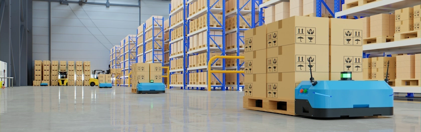
Autonomous Mobile Robots (AMRs) are able to carry out their jobs with zero to minimal oversight by human operators. Facilities such as schools, hospitals, shopping malls, and factories in particular can use a swarm of AMRs to improve operational efficiency and quality of life.
Learn MoreSemiconductor Solution

Everything is essentially driven by chips, and to suit the needs of diverse applications, a perfect wafer manufacturing process is necessary to ensure everything from quality to efficiency and productivity.
Learn MoreSmart Manufacturing
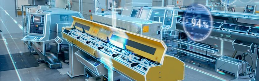
Fueled by edge computing, ADLINK smart manufacturing solutions guarantee faster data to decision results and create a more resilient and secured production environment for semiconductor and electronics manufacturing.
Learn More -
Strategic Partners
AMD-based Solutions
Empower your edge computing with ADLINK, a leading company enabling edge solutions. Leverage AMD's high performance, secure integration, and power efficiency advantages for a wide range of edge, networking, and edge systems with x86 core architecture. Experience superior processing and graphics performance with ADLINK's utilization of AMD EPYC™ Server CPUs and Ryzen™ Embedded series, powered by EPYC™ 9004/9005 Series CPUs and Radeon™ RX, perfect for industrial, medical, automation and gaming applications.
Learn MoreAmpere-based Solutions
Experience the future of edge computing with our comprehensive offering, which includes the Ampere Altra-based COM-HPC module, a developer platform and/or dev kit. Dive in now to unleash superior performance, energy efficiency, and optimized TCO in applications including but not limited to industrial automation, autonomous vehicles, transportation, healthcare, video surveillance, and energy management.
Learn MoreArm-based Solutions
Based on Arm architecture, ADLINK also collaborates with Ampere, NXP, MediaTek, Qualcomm, and Rockchip in module computing development and value-added solutions across varied industries, including smart manufacturing, autonomous driving, robotics, AMR, drone, transportation, logistics, retail, infotainment, healthcare, security, and more.
With plug-and-play tools, development kits, and all-encompassing systems, ADLINK and Arm empower developers to accelerate and realize their innovations.
Learn MoreIntel-based Solutions
ADLINK is a Prestige Partner of Intel® Partner Alliance. From modular computing to system-ready use cases, ADLINK collaborates closely with Intel to deliver scalable, interoperable solutions that accelerate the deployment of intelligent devices with end-to-end analytics.
ADLINK leverages Intel® AI Edge Systems to deliver scalable, high-performance AI at the edge. Built on proven, benchmarked edge computing platforms, these solutions integrate GPU and NPU acceleration with enterprise-ready manageability to optimize real-world AI workloads. With long lifecycle support, industrial-grade reliability, and best-in-class TCO, ADLINK and Intel enable faster time-to-market and seamless AI deployment across diverse edge environments.
Learn MoreMediaTek-based Solutions
ADLINK Technology and MediaTek are strategic partners that deliver innovative and powerful solutions for edge computing and edge AI applications. Leveraging MediaTek's flagship, power-efficient Genio platform SoCs and ADLINK's expertise in embedded and rugged designs, they provide high-performance, energy-efficient, and reliable modules and platforms in accomplishing various IoT use cases, such as smart home, human-machine interface, multimedia, industrial IoT, and robotics.
Learn MoreNVIDIA-based Solutions
To fulfill industry-specific requirements, ADLINK is able to efficiently develop edge AI platforms, AI smart cameras, medical platforms, and AI portable GPU accelerators based on NVIDIA Jetson modules, the NVIDIA IGX platform, and RTX Embedded GPUs for applicable industries, including smart manufacturing, autonomous driving, autonomous mobile robots (AMR), robotics, transportation, healthcare, logistics, retail, infotainment, AI development, professional graphics, and gaming.
Learn MoreNXP-based Solutions
Utilizing NXP's i.MX 8 and i.MX 9 series technology, ADLINK offers edge-connected solutions to assist medical, test & measurement, automation, and smart city customers reduce TCO. This combination of NXP's technology with ADLINK's R&D experience in edge computing provides versatile and dynamic solutions for critical applications.
Learn MoreQualcomm-based Solutions
Qualcomm Technologies’ portfolio of leading robotics and drones solutions is driving next-generation use cases, including autonomous deliveries, mission critical use cases, commercial and enterprise drone applications and more.
Among them, the Qualcomm QRB5165 solution is designed to help build consumer, enterprise or industrial robots with 5G connectivity, on-device AI and machine learning, superior computing, and intelligent sensing capabilities. By adopting Qualcomm QRB5165, ADLINK’s module will enable the proliferation of 5G in robotics and intelligent systems.
Learn More
EdgeOpen™ Voices
Explore how experts are driving edge AI forward with real stories and practical insights.
VISIT NOW -
Support

No matter you need to get product pricing and availability or need assistance with technical support, we are here for you.
Learn More - About

- Home
- Solutions
- Test & Measurement
- Technical Papers
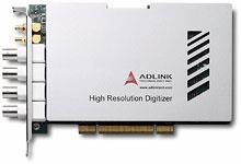
- Application of High-speed Digital Instruments in Testing Firework Products
- Home
- Solutions
- Test & Measurement
- Technical Papers
- Application of High-speed Digital Instruments in Testing Firework Products
English
繁體中文
简体中文
한국어
日本語
- Login
- home
-
Products
Industrial PCs, Motherboards, & SBCsEmbedded Computers & IoT GatewaysEdge AI PlatformsAI Smart CamerasRobotic ControllersIndustrial Solid State DrivesIndustrial Touch MonitorsRugged MonitorOpen Frame Panel PCsAll-in-One Panel PCsRugged Panel PCsDigital Signage Players/Compact Box PCsMini-ITX Motherboards Expandable Fanless Embedded PCs Integrated Fanless Embedded PCs ATX Motherboards Embedded Boards IPC Systems PICMG Single Board Computers Passive Backplanes Industrial Computer Peripherals Industrial Computer ChassisFrame Grabbers/Video Capture Cards Image Analysis Tool Smart Camera Vision Systems AI Machine Vision Device
-
Solutions
Edge AI
Powering the next wave of distributed intelligence, our Edge AI solutions offer a comprehensive portfolio that scales across all edge tiers—from low-power inference to demanding large model inference. Every system is built as an AI integrated system, featuring GPU/accelerator-ready I/O for true plug-and-play deployment. This design is GenAI-ready, delivering optimized performance for vision AI, predictive analytics, and efficient on-device LLM inference.
Learn MoreGaming
ADLINK Gaming provides global gaming machine manufacturers comprehensive solutions through our hardware, software, and display offerings. Uniquely combining computer expertise with a cutting-edge software stack and a deep understanding of the gaming industry’s requirements and regulations, we back up our customers so they can focus on creating the world’s best games.
Learn MoreMedtech
ADLINK delivers AI-ready, medical-grade solutions for healthcare innovation. Backed by strategic technology partnerships, 5–7 year lifecycle support, and extensive customization capabilities, we help medical device manufacturers accelerate development and bring reliable solutions to market.
Learn MoreRailway
Our Rugged by Design CompactPCI/CompactPCI Serial, computer-on-modules, industrial-grade system and panel computer product portfolio has been specifically selected for onboard ATO/DMI and wayside CTC/RBC/TSRS railway solutions. ADLINK’s exceptional flexibility in design and manufacturing has been utilized by top rail signaling providers worldwide.
Learn MoreRobotics
Autonomous Mobile Robots (AMRs) are able to carry out their jobs with zero to minimal oversight by human operators. Facilities such as schools, hospitals, shopping malls, and factories in particular can use a swarm of AMRs to improve operational efficiency and quality of life.
Learn MoreSemiconductor Solution
Everything is essentially driven by chips, and to suit the needs of diverse applications, a perfect wafer manufacturing process is necessary to ensure everything from quality to efficiency and productivity.
Learn MoreSmart Manufacturing
Fueled by edge computing, ADLINK smart manufacturing solutions guarantee faster data to decision results and create a more resilient and secured production environment for semiconductor and electronics manufacturing.
Learn More -
Strategic Partners
AMD-based Solutions
Empower your edge computing with ADLINK, a leading company enabling edge solutions. Leverage AMD's high performance, secure integration, and power efficiency advantages for a wide range of edge, networking, and edge systems with x86 core architecture. Experience superior processing and graphics performance with ADLINK's utilization of AMD EPYC™ Server CPUs and Ryzen™ Embedded series, powered by EPYC™ 9004/9005 Series CPUs and Radeon™ RX, perfect for industrial, medical, automation and gaming applications.
Learn MoreAmpere-based Solutions
Experience the future of edge computing with our comprehensive offering, which includes the Ampere Altra-based COM-HPC module, a developer platform and/or dev kit. Dive in now to unleash superior performance, energy efficiency, and optimized TCO in applications including but not limited to industrial automation, autonomous vehicles, transportation, healthcare, video surveillance, and energy management.
Learn MoreArm-based Solutions
Based on Arm architecture, ADLINK also collaborates with Ampere, NXP, MediaTek, Qualcomm, and Rockchip in module computing development and value-added solutions across varied industries, including smart manufacturing, autonomous driving, robotics, AMR, drone, transportation, logistics, retail, infotainment, healthcare, security, and more.
With plug-and-play tools, development kits, and all-encompassing systems, ADLINK and Arm empower developers to accelerate and realize their innovations.
Learn MoreIntel-based Solutions
ADLINK is a Prestige Partner of Intel® Partner Alliance. From modular computing to system-ready use cases, ADLINK collaborates closely with Intel to deliver scalable, interoperable solutions that accelerate the deployment of intelligent devices with end-to-end analytics.
ADLINK leverages Intel® AI Edge Systems to deliver scalable, high-performance AI at the edge. Built on proven, benchmarked edge computing platforms, these solutions integrate GPU and NPU acceleration with enterprise-ready manageability to optimize real-world AI workloads. With long lifecycle support, industrial-grade reliability, and best-in-class TCO, ADLINK and Intel enable faster time-to-market and seamless AI deployment across diverse edge environments.
Learn MoreMediaTek-based Solutions
ADLINK Technology and MediaTek are strategic partners that deliver innovative and powerful solutions for edge computing and edge AI applications. Leveraging MediaTek's flagship, power-efficient Genio platform SoCs and ADLINK's expertise in embedded and rugged designs, they provide high-performance, energy-efficient, and reliable modules and platforms in accomplishing various IoT use cases, such as smart home, human-machine interface, multimedia, industrial IoT, and robotics.
Learn MoreNVIDIA-based Solutions
To fulfill industry-specific requirements, ADLINK is able to efficiently develop edge AI platforms, AI smart cameras, medical platforms, and AI portable GPU accelerators based on NVIDIA Jetson modules, the NVIDIA IGX platform, and RTX Embedded GPUs for applicable industries, including smart manufacturing, autonomous driving, autonomous mobile robots (AMR), robotics, transportation, healthcare, logistics, retail, infotainment, AI development, professional graphics, and gaming.
Learn MoreNXP-based Solutions
Utilizing NXP's i.MX 8 and i.MX 9 series technology, ADLINK offers edge-connected solutions to assist medical, test & measurement, automation, and smart city customers reduce TCO. This combination of NXP's technology with ADLINK's R&D experience in edge computing provides versatile and dynamic solutions for critical applications.
Learn MoreQualcomm-based Solutions
Qualcomm Technologies’ portfolio of leading robotics and drones solutions is driving next-generation use cases, including autonomous deliveries, mission critical use cases, commercial and enterprise drone applications and more.
Among them, the Qualcomm QRB5165 solution is designed to help build consumer, enterprise or industrial robots with 5G connectivity, on-device AI and machine learning, superior computing, and intelligent sensing capabilities. By adopting Qualcomm QRB5165, ADLINK’s module will enable the proliferation of 5G in robotics and intelligent systems.
Learn More
EdgeOpen™ Voices
Explore how experts are driving edge AI forward with real stories and practical insights.
VISIT NOW -
Support
No matter you need to get product pricing and availability or need assistance with technical support, we are here for you.
Learn More - About