


- ホーム
- インダストリー
- 検査 & 計測
- Technical Papers
- Application of High-speed Digital Instruments in Testing Firework Products
日本語
Tang Jin-Wei,
Beijin Salientronics Co. Ltd.
Application
Testing of Firework Products
Challenge
Testing firework products entails a certain amount of danger, therefore high-standard requirements are imposed on ignition parts of the system. The ignition controller must be highly reliable, capable of ensuring dependable ignition for every single test; while at the same time resistance of relay contacts must be very low, so that it will not affect the ignition performance of the product.
Output performance tests of firework products are transient tests where signal alteration is very quick; it requires high-speed synchronized data capture boards for high-speed data registration.
Firework tests are non-repeatable and therefore require highly dependable data capture boards for ensuring the success of each test.
Firework products involve versatile parameters of output properties. While addressing different product properties, sensors of different types require the arrangement of agile and flexible signal conditioning modules.
Testing of firework products needs synchronized triggering of high-speed cameras, therefore requires capture boards with TRIG IOs for triggering other peripheral devices.
Solution
Based on the design and implementation of a test system with multi-state parameters, via understanding and adjusting signal characteristics of firework product output parameters and commonly used test methods, performance indexes of instruments are analyzed and summarized for the precision testing of output performances of firework products. Combining proper sensors for pressure, temperature, push-force, etc., and hardware facilities such as signal regulators and process controllers equipped with the ADLINK PCI-9846D high-speed data capture card, an ignition controller is designed based on customer requirements, enabling a system not only possessing autonomous detection functions that enhances the safety of the operator when carrying out ignition tests, but also realizing the switching-over between manual and automated triggering. A data retrieval and analysis program for a multi-parameter testing system of firework products is developed using LabVIEW as the development platform. The system incorporates a programmable signal conditioner and functions including data capture, analysis and process, data storage, representation, report compilation; etc.
Firework products is the nomenclature of one-time-use elements or devices, containing gunpowder or explosives which burns or explodes when receiving an external stimulation, used for igniting gunpowder or detonating explosives or doing mechanical work. Firework products are usually used for igniting gunpowder and detonating explosives, or as small drive devices for promptly opening a valve, releasing a safe, or separating a rocket stage.
According to regulations of Nomenclature of Civilian Explosives, GB\T 4659-2003, firework products are generally categorized as follows.[1]
Based on output characteristics, firework products can be categorized into 3 types: igniting fireworks, detonating fireworks, and other fireworks, as detailed in Table-1.
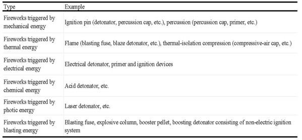 Table-1 Categories of Fireworks, by output characteristics
By structure, fireworks can be divided into simple fireworks and complex fireworks.
Fireworks can be triggered by 6 forms of energy, namely mechanical energy, thermal energy, electrical energy, photic energy, chemical energy, and blasting energy. By type of input triggering energy, fireworks can be categorized as detailed in Table-2.
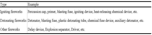 Table-2 Categories of Fireworks, by type of input triggering energ
There are many output performance parameters of firework products, such as pressure, push-force, temperature, impact acceleration, displacement, acting time, bridge-wire melting time, delay time, etc. These performance parameters are obtained by providing sufficient voltage and current to the tested product, so as to trigger the activation of the firework product, therefore recording output parameters of the product. In order to carry out various performance tests of versatile firework products using a single set of equipment, and for better and more comprehensive use of the test system, it is necessary to design a comprehensive test system that can be applicable to various firework products. With such a system, multiple parameters of product output performances can be obtained via one simplified test process, providing abundant information for the design of product performances and for the research of functioning mechanisms, as well as providing valuable references for product quality design and for lowering development costs.[2]
Problems encountered
Testing firework products entails certain hazards, therefore high-standard requirements are imposed on the ignition part of the system. The ignition controller must be highly reliable, ensuring dependable ignition of each test; at the same time, the resistance of relay contacts must be very low, so that the ignition performance of the product will not be affected.
Output performance tests of firework products are transient tests where signal alteration is very quick; it requires high-speed synchronized data capture boards for high-speed data registration.
Firework tests are non-repeatable, and therefore require highly dependable data capture boards for ensuring the success of each test.
Firework products involve versatile parameters of output properties. While addressing different product properties, sensors of different types require the arrangement of agile and flexible signal conditioning modules.
Testing of firework products requires synchronized triggering of high-speed cameras and therefore requires capture boards with TRIG IOs for triggering other peripheral devices.
Solution
Based on the demand for configuring a test system, via a market survey of relevant products available in the marketplace, we selected the DEWETRON signal conditioning module and the ADLINK PCI-9846D high-speed data capture card as the infrastructure, and, combined with self-produced ignition controllers, quickly developed an instrument suitable for testing versatile firework products.
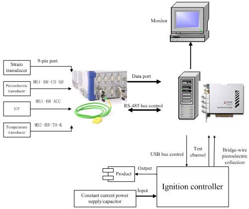 Fig. 1 System Configuration
The system comprises sensors, a signal conditioner, a process controller and an ignition controller. The system works as follows: When process controller commands, via USB port, the ignition controller to close relay contact, the firework product is therefore in the state of ignition; at this moment, the product bridge-wire will melt instantly to generate a short pulse of voltage signal, i.e., the bridge-wire melting signal and the signal of pressure or push-force acting upon the product. Different sensors are used for testing physical responding signals; weak voltage signal output or electric charge signal output by the sensor is sent to the signal conditioner for amplification up to 5V with high frequencies filtered out. Amplifier gain and filter frequency are set by the process controller via the RS-485 bus. The conditioned signal can thus be read by the capture card. The signal alters quickly, therefore high-speed cards are used for measurement. On completion of tests, data processing and data analysis, data storage and report generation are carried out by the program of the system.
1. Signal conditioner
To meet the requirement that 4 channels of the data capture system shall be capable of connecting with different sensors, i.e., the function of universal channels, the system employs a Dewetron DEWE-31-16 signal conditioner [3].
(1)Major performance indexes of the amplifier:
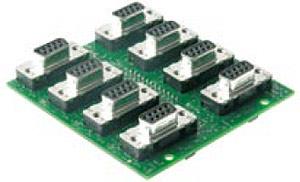 Fig. 2 Amplifier
(2)Filter board major performance indexes:
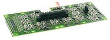 Fig. 3 Filter board
2. Capture card ---PCI-9846D high-speed capture card [4]
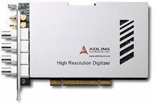 Fig. 4 PCI-9846D
3. Ignition Controller
The function of the Ignition Controller is for regulating ignition current, carrying out autonomous inspection of circuit connection, and igniting the product during firework tests.
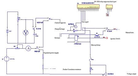 Fig. 5 Schema of ignition controller
When constant-current source is used for igniting the product, it is necessary to regulate the ignition current for the product. Firstly, use an ohmmeter to test product resistance. Based on this resistance, adjust the potential meter R7 to the said value and use it as a substitute of product resistance, for current regulation. Then adjust ignition current to the design value, using the voltage knob of power supply and the external potential meter RP2.
When a capacitor is used for igniting the product, firstly move S1 switch to the "Charge" position for charging the capacitor with the battery. By checking the capacitor charge voltage via the static voltage meter, move S1 switch to the "Discharge" position and prepare for ignition.
Before carrying out ignition, make an autonomous inspection; i.e., check the entire ignition circuitry for correct connection. This can be done by ensuring the product is in a condition such that it will not be activated, closing the relay of the autonomous inspection circuit, and checking for any reading of current flowing through the circuit. According to product properties, the current for autonomous inspection must be less than 5mA to ensure that the product is not activated. Therefore, a series resistance required for the autonomous inspection circuit can be calculated based on the maximum ignition voltage of the product.
For the formal ignition test, in order to eliminate any effect caused by the sampling resistor, the system uses a mercury relay in the ignition circuit. The contact resistance of this type of relay is extremely low and can be omitted, thus eliminating any influence to the product's ignition performance resulting from the circuit.
4. Test method
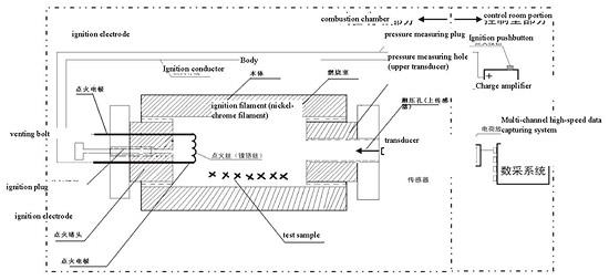 Fig. 6 Test Method
For pressurized products, the test system consists of an on-site portion and a control room portion. Since the testing of enclosed detonators contains a certain amount of danger, the detonator body, plug, pressure sensor and other relevant parts are all placed at the test site, while the ignition control and data capture parts are within the control room, with safety insulation provided between these two portions.
When carrying out the test, after loading test charges in the detonator, transient high-voltage is applied to the ignition resistance filament so its temperature rises and it becomes red, igniting the ignition charge and therefore the test charge. This causes the pressure in the combustion chamber to rise, causing a corresponding alteration of the sensor and an output of a transient voltage, the waveform alteration of which is captured by the high-speed data capture system and registered as the basis of subsequent analysis. Since the test process of the enclosed detonator is very brief, quality pressure sensors and high-speed data capturing systems are essential for ensuring precise and timely capture of the test data. See Fig.6.
In the process for testing firework products, voltage alteration across the resistance is measured before the bridge filament melts down. The test procedure is as follows:
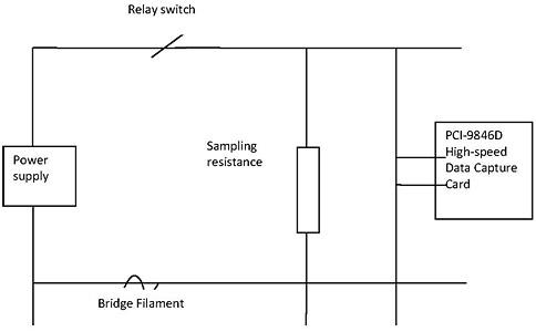 Fig. 7 Product detonation
As shown in Fig. 7 when the relay switch is open, the circuit is open and no current flows through the bridge filament, therefore there is no voltage on the sampling resistance. When the relay switch closes, the bridge filament is energized and a high voltage occurs across the sampling resistance; at this moment the firework product ignites and produces high temperatures which cause the bridge filament to melt out, therefore breaking the circuit, and the voltage across the sampling resistance resumes its previous low level. This melting process takes hundreds of microseconds to a few milliseconds. The signal frequency of the voltage alteration is from around a few kHz to tens of kHz.
5. Software Design
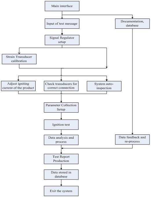 Fig. 8 Program Flowchart
The application software is a program developed by the developer using instrument drivers for direct operation by the user. Via direct viewing of the user-friendly interface, abundant functions of data analysis and processing, as well as comprehensive data storage functions, the software completes the test tasks automatically.
Application software of virtual instrumenst can be developed according to personal preferences and specialties using various software development environments. There are two major development environments: one is based on a text software development platform, such as Visual C++, Visual Basic, Delphi or LabWindows/CVI, etc. The other is based on a graphic software development platform such as VEE or LabVIEW.[5,6,7] Our system uses LabVIEW as the development platform of the system program.
The system software can be divided into several function modules: test data input, signal conditioner, system calibration, system auto-inspection, data capture and processing, data storage, report production, data replay and re-processing. The modular design structure enables clear and neat programs as well as facilitating future expansion and upgrade services.
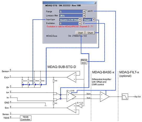 Fig. 9 Device Interface
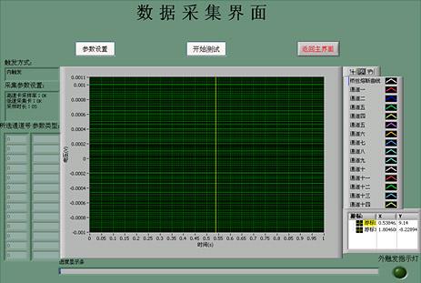 Fig. 10 Data Capture Interface
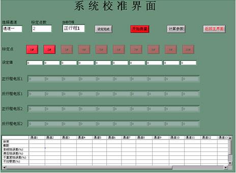 Fig. 11 System Calibration Interface
The main purpose of the signal conditioning module is to integrate programs—which are used by DEWETRON's DEWESoft for the control of signal conditioning—into LabVIEW, thus realizing the requirement of separately setting up the signal conditioner of the system software. Using the ActiveX control item container[8], it is possible to borrow ActiveX control items provided by DEWETRON and successfully conduct program control against the signal conditioner based on the programmer manual[9] of DEWESoft. The System Calibration is mainly addressing the use of a resistance type strain sensor, which requires using a piston pressure machine against the entire system for carrying out the calibration. Tests can only be carried out when non-linear errors, lag errors, non-zeroing errors and non-repetitive errors meet the requirements of national military standards. Tests must also mark points and corresponding voltage values, using the least square method for calculating the slope and intercept of the linear relationship between the test system and signal conversion in accordance with the principle of least sum of deviation squares, for the conversion of engineering units. For the conversion of engineering units of tungsten rhenium thermocouples, an interpolation calculation is required based on the table of thermocouple scales. When using graphic programs in LabVIEW for carrying out large amounts of calculations, the program tends to become complicated and operates slowly. Therefore, equation nodes can be used by adding program numbers to nodes, thereby significantly simplifying the program and speeding up the calculation.
The system software provides abundant data analysis and process functions; after processing the data, the system produces professional test reports using the Office Tool Pack[10] of LabVIEW, and stores data files in the TDMS format. Via Access database, a file is generated for each test based on the test time, product name and operator, together with a path for storing the file in the database. Thus, when replaying the data for reprocessing, the position of the previous file can be sorted via the time, operator, or the product name. When clicking on the format series number, the system will send the data file path of the current registration to the system, for the Data Replay Module to quickly retrieve the previous data for reprocessing. The user may also delete files of ineffective data here. By way of database management, the user is significantly facilitated in searching for and using large amount of data files and the system is further perfected. Due to the importance of the test data, precautions must be taken to avoid mistaken deletion before deleting any file. Therefore the database provides the function for opening a corresponding binary data reserve file; by viewing test results via this file, it can be ensured that a file will not be mistakenly deleted. The user may select a sorting index in the Project draw-down tab menu for a specific query, and key-in corresponding query criteria in the box of query conditions. on clicking the Query button, the table will display all the data files that comply with the criteria. By using the serial number selection box, the user can select a file to be processed, i.e. opened, deleted, etc. The OPEN function allows the user to open a desired file, displaying data in the data replay and reprocessing interface, for carrying out secondary data analysis and processing. Professional and complete test analysis software will provide the user with a System Help function, facilitating the user to view the operating instructions of the program. This system program also provides a Help text file of its own, it may be called by way of clicking the Help icon. In LabVIEW, the simplest way to activate other Windows application programs is to execute a system command. Inputting a DOS command in the command line may activate the Help file; this is the most simple, convenient and effective method.[11]
Test
1. Test Bench
Each product should have its own test device. For example, a product used to measure pressure must be ignited in a pressure-testing bullet with an appropriately-sized capacity in order to obtain the expected data. A thrust-related product must be clamped on a Test Bench and securely connected with a Thrust Tester. As more testing parameters would be required for a separated push rod product, the installation position of each tester should also meet the technical requirements. Introduced below is a summary of some typical test benches.
(1) Pressure Testing Vessel
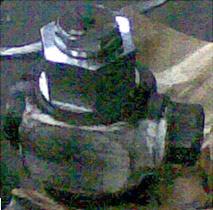 Fig. 12: Pressure Testing Compartment
(2) Thrust Test Bench
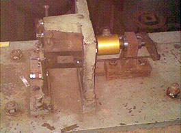 Fig. 13: Motor Test Bench
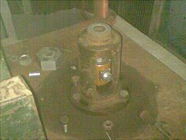 Fig. 14: Thrust Test Bench
2. Experimental Test
(1) Purpose[12]
Test the pressure-time and thrust-time curves for the ignition of firearm, in order to evaluate its change of output performance over time.
(2) Theory
By applying the specified excitation energy to the firearm clamped in the Pressure-Testing Compartment, the gas generated from the ignition of the firearm will act on the Tester by outputting an electrical signal corresponding to the parameter change, such as pressure and thrust. After being conditioned by the Signal Modulator, relevant data will be read by the PCI-9846D High-speed Data Acquisition Card.
(3) Experiment program
(a) Connect the test system.
(b) Set the capacity of the selected Pressure-testing Compartment in order to determine the Sensor to be used.
(c) Connect the ignition wire and then modulate the igniting current.
(d) Mount the Sensor on the Piston-type Pressure Gauge and then connect the Sensor and the Signal Modulator.
Before each test, it is necessary to execute the Static Pressure Setting for the Sensor. Normally, the set pressure interval should not be less than 4 counts and each pressure interval should be equivalent. When setting the static pressure, it is necessary to perform the boosting and reducing process twice respectively. The technical index of the static pressure setting shall meet military requirements; otherwise, the causes should be determined in order to take relevant action (e.g. replacing the sensor) and then proceed with the setting until the requirements are satisfied.
(a) Mount the programmed sensor together with the Test Subject on the Pressure-testing Compartment and then seal properly.
(b) Secure the Pressure-testing Compartment containing the Test Subject and the Sensor, and then connect the Sensor wire, ignition wire, detonating wire and other relevant wires for the system to be put into test ready status.
Execute a self-inspection for the connecting condition of the product with the self-inspection function designed for the system. If the self-inspection is failed, then check if the power is turned on, if the Ignition Controller is energized, and if the product ignition clamp is properly connected, etc. After passing the self-inspection, the ignition test will follow in order to collect the data.
(4) Data Processing and Product Performance Analysis
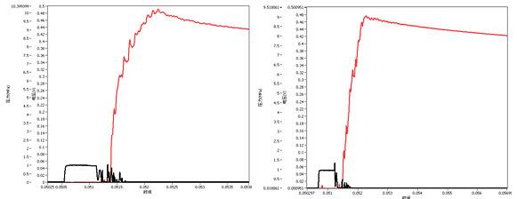 Fig. 15: Product 1
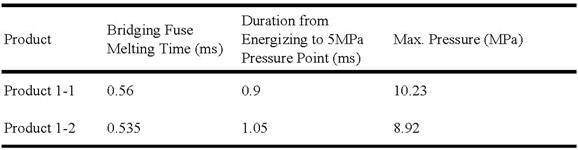 Table 3: Main Technical Parameter Comparison between 2 Rounds of Experimental Tests for Product 1
Conclusion: The result indicates that the melting time of the bridging fuse is less than 1ms; the duration from energizing to 5MPa pressure point is shorter than 10ms; and the max. pressure is over 8.5MPa. As such, the result complies with the performance requirements of Product 1 and it justifies the correctness of the system in data collection.
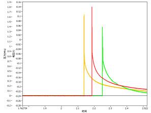 Fig. 16: Product 2
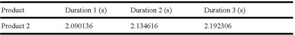 Table 4: Main Technical Parameters of Product 2
Conclusion: The result indicates that the duration from energizing to action is less than 2.5s, affirming the fidelity of the experiment in data collection.
 Fig. 17: Product 3
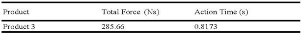 Table 5: Main Technical Parameters of Product 3
Through the understanding, modulation and study of signal features and regular testing methods for firearm output performance parameters, this article uses the design and realization of Firearm Multi-type Parameter Test Systems as the background to analyze and summarize the instrument performance indicator required for accurately testing the firearm output signal. Suitable hardware equipment consisting of sensors, signal modulators, the ADLINK PCI-9846D high-speed data acquisition card and engineering controllers etc. are selected for the pressure, temperature and thrust, etc. in order to test the performance parameters. Aiming to satisfy the user's demand, we also designed the Ignition Controller which not only provides a self-inspection function for the system but also improves the safety of the operator when conducting the Ignition Test, while achieving the switching between manual/automatic ignition. In addition, we also implemented the LabVIEW software development platform which allows a single set of data acquisition and analysis software to be developed for the Firearm Multi-type Parameter Test System. In this regard, the said system is also designed with functions such as program control device, signal modulator, data acquisition and analysis processing, data preserving, playback and report producing, etc. in mind.
Through the field firearm experimental test at the user's site and the analysis of the said test, the result has demonstrated the soundness of the system design and has met the application requirements of the user.
Reference
[1] XIA Jian-Tsai, LIU Li-Mei: Firearm Manufacturing. Beijing: Beijing Institute of Technology Publication Service, 2009, 8:1-10.
[2] FU Yung-Jieh, YEN-Nang: Analysis and Test of Firearm Gas Output Dynamic Parameter Characteristics; Explosive Academic Journal. 2007, 6; Vol. 30, Edi. 3.
[3] DEWE-MDAQ series Technical reference manual. DEWETRON INC
[4] PCI-9816/26/46 User's Manual. ADLINK TECHNOLOGY INC.
[5] TSUI Hung-Mei: Virtual Instrument Design and Application Research facing toward the Test System; Inner Mongolia Agricultural University doctorate dissertation; 2007.4
[6] LIU-Gang, WANG Li-Xiang, ZHANG Lien-Fa: LabVIEW 8.20 Chinese Version Compilation and Application; Beijing: Electronic Industrial Publication Service, 2008
[7] CHEN Xi-Hui, ZHANG Yin-Hung: LabVIEW 8.20 Program Design- Basic to Advanced. Beijing: Tsinghua University Publication Service. 2007
[8] Active X Control Item. http://baike.baidu.com/view/185274.htm.
[9] Programmer's Reference to the DCOM Interface of DEWESoft 6.4.DEWETRON INC.
[10] ZHANG Su-Juan, WANG Tien-Bao: On LabVIEW Data Interview and Report Producing Techniques. Chengdu Information Institute of Engineering Journal. 2009, 4; Vol. 24, Edi. 2
[11] Robert H. Bishop. LabVIEW Practical Courses. Beijing: Electronic Industrial Publication Service. 2008
[12] GJB5309.24: Firearm Experiment Method. Part 24: Ignition Pressure - Time Curve Measurement
Related ADLINK Links: