


- ホーム
- インダストリー
- 検査 & 計測
- Technical Papers
- An Inverter Output Performance Test System
日本語
ZANG Yi,
Henan Industrial University
Application
Inverter based speed regulation for motors of high-voltage and power
Challenge
A high-voltage inverter employs multiple cascaded low-voltage power units for high-voltage output with good fault tolerance. In case of component unit(s) failures, the system can maintain normal operation with reduced capacity for steady production by masking the fault units along with specific troubleshooting measures. This study designs a system for real-time monitoring and analysis on a range of indicators of output power quality from unit cascaded high-voltage inverters employing three troubleshooting measures. The proposed design focuses on maintaining the same output voltage performance before and after unit failure to minimize failure-related impacts on system operation.
Solution
The PCI-9846 based inverter output performance testing system employs a system control console built with the LabVIEW virtual instrument software platform to obtain reference waves under different troubleshooting measures addressing corresponding consoles. Tests are conducted on multi-unit cascaded inverter simulators and retrieve 3-phase voltage signals with the ADLINK PCI-9846 digitizer for analysis. Key performance benchmarks including amplitude, frequency, and total harmonic content of three-phase voltage phase, are acquired to check output status under normal and abnormal operation with different control algorithms.
Power-saving inverter driven motors meet domestic requirements of saving energy and emission reduction. For high-voltage and large capacity applications inverter devices are deployed with high-voltage large-capacity switches and multi-level topology structures. The cascaded inverters are multi-level inverters with good application potential. They are adopted by mission critical applications, e.g., driving fans and pumps, requiring reliable and non-stop operation (at reduced capacity) even in case of system failure. The energy saving benefits of high-voltage inverter driven motors requires system reliability at the same time. That is, the high-voltage inverter devices must feature fault tolerance to ensure continuous system operation by masking failed assemblies and modules and running alternative control mechanisms automatically.
A high-voltage inverter employs multiple cascaded low-voltage power units for high-voltage output with good fault tolerance. In case of component unit(s) failures the system can maintain normal operation with reduced capacity for steady production by masking the fault units along with specific troubleshooting measures. Typical troubleshooting measures mask off the failed unit while running modules in the other two phases to maintain the balanced operation of the inverter. The wasted capacity of these two units mandates further studies on the troubleshooting measures taken by cascaded inverters in normal and fault operation modes. The PCI-9846 digitizer-based inverter output performance testing system proposed by this study performs real-time monitoring and analysis on various quality indicators of output power provided by unit cascaded high-voltage inverters after different troubleshooting measures�Xthree in this study�Xwere taken. Performance indicators of the system output voltage must maintain the same level before any unit failure to minimize impacts of system failure on operations. This testing system employs a system control console built with the LabVIEW virtual instrument software platform to obtain reference waves under different troubleshooting measures addressing corresponding consoles. Tests are conducted on multi-unit cascaded inverter simulator and retrieve 3-phase voltage signals with the ADLINK PCI-9846 digitizer for analysis. Key performance benchmarks including amplitude, frequency, and total harmonic content of three-phase voltage phase are acquired to check output status under normal and abnormal operation with different control algorithms.
Structure and mechanism of unit cascaded high-voltage inverter
The unit cascaded high-voltage inverter employs multiple cascaded low-voltage power units for direct high-voltage output with structure outlined in Figure 1. The H bridges, see Figure 1, are multi-isolation transformers with a primary side for high-voltage input and a secondary for isolated low-voltage output to individual power units. Each of the system's three phases features one three-phase input and a one-phase output AC-DC-AC inverter of unified structure. See Figure 2 for the structure of the power unit.
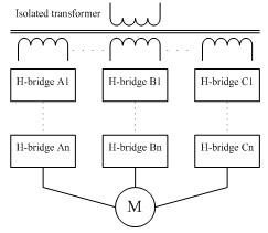 Figure 1: Structure of unit cascaded inverter
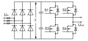 Figure 2: Structure of power unit
The power unit is powered by one secondary winding of the input transformer. The power units and secondary windings are insulated from themselves and each other. When cascaded in six units for each phase then each unit is subject to the total output current but 1/6 of the output phase voltage and 1/18 of the output power. For a 6KV motor system the output voltage and frequency of each unit can be individually regulated in the range of 0~590V and 0~50Hz for inverter control.
The power unit of a cascaded high-voltage inverter employs carrier phase shift PWM control technology. The inverters shown in Figure 1 are modulated by n-pairs of triangle carriers phase shifting 60o/n in sequence against the fundamental voltage. A 2*n+1 levels of hierarchical phase voltage wave can be generated by stacking up a total of n of each signals modulated by A-phase base carrier control n pieces of power units, A1��An. This is equivalent to a 6*n pulse frequency conversion which offsets all the harmonics below 6*n-1 and leads to total voltage and current distortion as low as around 1%. This can certainly be considered a perfect harmonic free inverter. Power units in one phase of the inverter output the same fundamental voltage. By cascading carriers of each unit at equally staggered phases, then a 12KHz equivalent output phase voltage switch frequency can be acquired by cascading 6 power units, with IGBT switch frequency at 1KHz, from each phase. Power units with low switch frequency reduce switch loss while high equivalent switch output frequency and multiple levels improves output waveform significantly. Better waveforms not only reduce output harmonics but also reduce noise, du/dt value and the motor's torque ripples. All of these enable the inverter to impose no special requirements on motors when applied in speed regulation power. This kind of inverter is suitable for general high-voltage motors without derating and special limits on length of output cables.
Analysis on troubleshooting measures for unit cascaded high-voltage inverter
To ensure the unit cascaded inverter keeps running even with some failed power units for enhanced reliability, it is common to mask off the failed unit together with running modules in the other two phases to maintain the balanced operation of the inverter. This leads to wasted capacity of two units in normal condition and reduced maximum output capacity. However, this approach enjoys the merit of simplicity in theory and maturity in technology.
Neutral point shift (NPS) technology may be used to improve output performance of a multi-level inverter by making the most of the remaining normally functioning units. The neutral point of an inverter is floating and not connected to the center point of load (as shown in commonly available 3-phase motors). This enables the neutral point of an inverter to be away from the load center. Unbalanced three-phase voltage of an inverter's output can change to three-phase balanced load line voltage by regulating the phases of voltage. This regulation measure is equal to exiting a three-phase symmetric line voltage by stacking a zero sequence component to asymmetric output voltage from remaining units in each phase after the failure of some of them. As center points are not connected directly, this line voltage can ensure symmetric and steady operation after symmetric load phase voltage is generated over line voltage load. As the three phases are not symmetric to each other, the conventional optimization control approach of injecting a third harmonic for improved unit voltage utilization rate does not apply any more. The neutral point shift approach does not make the most of system output capacity. In certain system failure cases, the maximum output capacity is even worse than the conventional approach of masking the failed unit and wasting the other two units in the remaining phases.
This document [2] proposed a simple reference wave generation mechanism to replace the sine wave for inverter unit control. It makes the most of output capacity of each unit, improves the total output of the system, and reduces impacts of failures on load without changing current troubleshooting measures. It has the merits of simplicity and ease of use, and can be employed by changing the shapes of reference waveforms in accordance with failure types in the carrier control system and requires little modification to current troubleshooting mechanisms. It requires no shift angle calculation compared with the neutral point shift method.
Take the example of a six-unit cascaded system. The troubleshooting methods and output status when one unit in phase A fails are shown in Figure 3.
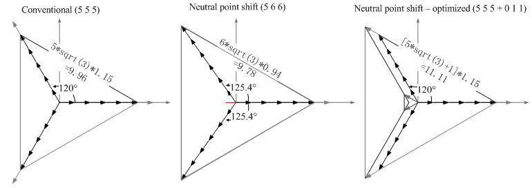 Figure 3: The three troubleshooting methods
A test system based on LabVIEW and PCI 9846
This study builds a test system with the LabVIEW virtual instrument software platform and ADLINK PCI 9846 high-speed digitizer to verify output performance of cascaded inverters under the three troubleshooting measures described above. The LabVIEW features graphic system design concepts and unique parallel data flow characteristics, and has merits in console interface creation, troubleshooting method design, signal collection and voltage signal performance analysis. As the equivalent output phase voltage switch frequency of cascaded inverters are multiple times that of individual switch devices, and as output voltage harmonics are concentrated in higher bands, it mandates better sampling rates provided by data gathering devices for analyzing inverter output characteristics. Normal data gathering devices can hardly meet such high sampling demands. The modularized instrument PCI 9846 features high sampling rates, up to 40MHz, with precision and good compatibility. With four embedded high-linearity 16-bit high precision A/D and four channels for concurrent sampling the PCI 9846 is ideal for the collection and processing of 3-phase output high frequency signals from cascaded inverters. The LabVIEW drivers provided by ADLINK reduces system development cycles as there are almost no compatibility issues.
See Figure 4 for block diagram of a cascaded inverter's output characteristics test system based on the LabVIEW virtual instrument software platform and ADLINK PCI 9846 digitizer.
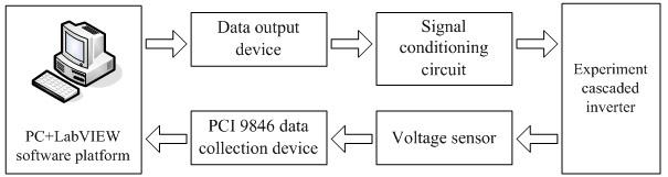 Figure 4: The test system block diagram
The said system used a PC to code control solutions and generate corresponding control signals in the LabVIEW virtual instrument platform, according to the three troubleshooting mechanisms described above. The control signals generated by the switch devices then send the data output device to the signal conditioning circuit for processing and transferral to the experiment cascaded inverter. The output signals from the inverter are then sent to the PCI 9846 via the sensors and collected by the data capturing programs in LabVIEW for high-speed collection and storage. The LabVIEW analysis software then analyzes collected signals to finish the cycle of characteristics analysis for output from the cascaded inverter.
Signal collection and analysis results
See Figure 5 for the console menu of the test system's LabVIEW virtual instrument platform. A sample analysis on a six-unit cascaded system is presented here along with reference waveforms derived from different troubleshooting mechanisms. See below for a review on the reference waveform equivalent phase voltage and the derived equivalent line voltage waveforms.
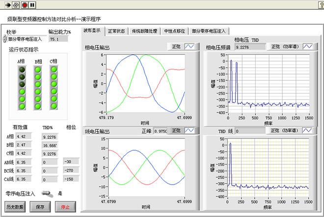 Figure 5: The main menu of the test system
Three troubleshooting mechanisms are used in the demo program with brief descriptions on working theories in each option tab. The indicator lights to the left suggest operation status of a six-unit cascaded inverter. An off indicator means a failed and masked unit. The operation status of three failed units in Phase A is shown in Figure 5. The system output capacity can be seen on top of the indicator lights. It shows that the system maintains near 75% output capacity in case of three failed units in Phase A with an optimized regulation method of injecting partial zero sequence voltage. This is much better than the 50% output capacity of the conventional system. Output from unified effective phase and line voltages, total harmonic distortion of phase voltages, and phases of 3-phase line voltages are displayed in a frame below indicator lights. The option tab to the right provides 3-phase phase voltages, output waveforms of line voltage, and harmonic analysis for one phase of the three. The zero-sequence voltage injection method is available for improved system output capacity by better DC voltage use. The operation results suggest that the proposed troubleshooting method masks failed units only. This leads to asymmetric phase voltages. However, the line voltage output retains equal amplitude and three phase balance and without a third harmonic component by regulating by regulating amplitudes and phases according to types of failures.
Output performances under various types of failures can be seen in Table 1. The Failure Type column gives the total number of normal units left in each of the three phases, e.g. (466) indicates that there are 4, 6, and 6 units working in phase A, B, and C respectively. That is, 2 units in phase A have failed. The maximum output capacity under each troubleshooting method is 66.70%, 76.30%, and 83.40%. respectively. It is clear now that the optimized neutral point shift with partial zero sequence voltage injection troubleshooting method gives the maximum system output for almost every failure type.
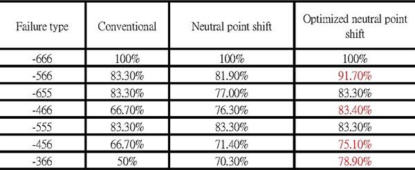 Table 1: Output performances by different troubleshooting methods
This study compared three troubleshooting measures in handling failures of cascaded inverters. An output characteristics test system for six-unit cascaded inverter has been built with the LabVIEW virtual instrument software platform and the ADLINK PCI 9846 high speed digitizer for testing and analyzing the effects of three different troubleshooting measures, including quality benchmarks of amplitude, frequency, total harmonic content, and phases of the three-phase voltage. The optimized neutral point shift with partial zero sequence voltage injection troubleshooting method proves a better troubleshooting mechanism for cascaded inverters as it gives the maximum system output and improves fault tolerance.