• 購物車(0)
繁體中文
English
简体中文
한국어
日本語
繁體中文
  • 登錄
  • 產品
    嵌入式模組化電腦
    • COM-HPC
    • COM Express
    • OSM
    • SMARC
    • Qseven
    • ETX
    GPU解決方案
    • MXM GPU 模組
    • PCIe 顯示卡
    強固型運算
    • CompactPCI & CompactPCI Serial
    • VPX
    • PC104
    • AVA Railway Rugged Computers
    • PIDS
    邊緣運算平台
    • 工業電腦 / 主機板 / 單板電腦
    • 嵌入式電腦 / IoT Gateway
    • 邊緣 AI 運算平台
    • AI 智慧相機
    • 機器人控制器
    • 工業級固態硬碟 (SSD)
    工業級顯示系統與平板電腦
    • 工業級觸控顯示器
    • Open Frame 平板電腦
    • All-in-One 平板電腦
    • 強固型面板電腦
    • 數位看板播放器
    車用解決方案
    • 自動駕駛解決方案
    • AI-ADAS 解決方案
    網路通訊與伺服器
    • AI GPU 伺服器
    • 工業級邊緣伺服器
    • 網路安全平台
    • P5G 工業自動化專網-MicroRAN
    自動化與控制
    • 機器視覺
    • 運動控制與 I/O
    • EtherCAT 運動控制解決方案
    • HMI 平板電腦
    • 資料擷取模組
    • GPIB 與數字化儀
    • PXI 平台與模組
    • 自主移動機器人
    • 工業物聯網閘道器
    設計與製造服務
    • DMS+ (ODM/OEM 服務)
    醫療專用電腦與顯示器
    • 醫療專用觸控電腦
    • 醫療專用顯示器
    • 醫療專用 BOX PC
    軟體
    • EdgeGO
  • 產業
    車用解決方案 軍工與航太 娛樂資訊 智慧醫療 半導體解決方案 智慧製造 鐵路 機器人技術

    車用解決方案

    車用解決方案

    凌華科技的自動駕駛運算平台採用尖端技術,致力提供更安全、更高效的駕駛運行。以強大的運算能力,滿足自動駕駛和先進駕駛輔助系統(ADAS)技術,並提供適用於汽車的堅固設計。

    了解更多

    軍工與航太

    軍工與航太

    在軍工航太領域中,準確觀察環境並做出快速可靠的決策並及時採取行動至關重要。 凌華科技強固的系統和Data Distribution Service(DDS)是大型數據基礎架構的關鍵,該基礎架構可收集、儲存、分析資訊並將資訊從現場傳遞給決策者。

    了解更多

    娛樂資訊

    娛樂

    凌華科技博弈平台解決方案透過我們的軟、硬體和顯示產品為全球遊戲機製造商提供全面性的服務。 我們將電腦專業知識與尖端軟體完美結合,並遵循博弈產業的要求和法規限制來為我們客戶提供服務,使他們能夠專注於打造世界上最好的娛樂體驗。

    了解更多

    智慧醫療

    智慧醫療

    凌華科技專注於醫療可視化設備和經過醫療認證的解決方案,來滿足智慧醫療數位化的需求。 透過PENTA在醫療領域的設計和製造能力,凌華科技的智慧醫療解決方案可加速各種醫療環境中的智慧轉型。

    了解更多

    半導體解決方案

    半導體解決方案

    你所能想像的一切,都因晶片而有所改變。為了滿足不同應用的需求,完美的晶圓製造對於品質的工藝要求到效率和生產力的過程都無比講究。

    了解更多

    智慧製造

    智慧製造

    借由邊緣運算,ADLINK 智慧製造解決方案加速更快的數據決策,為半導體和電子製造業創造更具彈性和安全性的生產環境。

    了解更多

    鐵路

    鐵路

    我們的強固設計 CompactPCI、模組化電腦、工業級系統及平板電腦系列產品特別獲選納入車載 ATO/DMI 及軌旁 CTC/RBC/TSR 鐵路解決方案。凌華科技在設計和製造方面的卓越靈活性廣受全球鐵路號誌領導供應商的青睞。

    了解更多

    機器人技術

    機器人技術

    自主移動機器人(AMR)能夠在沒有或最低限度的人工操作監督之下來執行工作。在一些可以使用大量的AMR設施譬如學校、醫院、大型購物中心和工廠之類的,以提高營運效率和生活品質。

    了解更多
  • 策略夥伴
    AMD Ampere Arm Intel MediaTek NVIDIA NXP Qualcomm

    AMD-based Solutions

    AMD-based Solutions by ADLINK

    Empower your edge computing with ADLINK, a leading company enabling edge solutions. Leverage AMD's high performance, secure integration, and power efficiency advantages for a wide range of edge, networking, and edge systems with x86 core architecture. Experience superior processing and graphics performance with ADLINK's utilization of AMD Ryzen™ Embedded series, powered by Radeon™ RX, perfect for industrial, medical, automation and gaming applications.

    Learn More

    Ampere-based Solutions

    Ampere-based Solutions by ADLINK

    Experience the future of edge computing with our comprehensive offering, which includes the Ampere Altra-based COM-HPC module, a developer platform and/or dev kit. Dive in now to unleash superior performance, energy efficiency, and optimized TCO in applications including but not limited to industrial automation, autonomous vehicles, transportation, healthcare, video surveillance, and energy management.

    Learn More

    Arm-based Solutions

    Arm-based Solutions by ADLINK

    Based on Arm architecture, ADLINK also collaborates with Ampere, NXP, MediaTek, Qualcomm, and Rockchip in module computing development and value-added solutions across varied industries, including smart manufacturing, autonomous driving, robotics, AMR, drone, transportation, logistics, retail, infotainment, healthcare, security, and more.

    With plug-and-play tools, development kits, and all-encompassing systems, ADLINK and Arm empowers developers to accelerate and realize their innovations.

    Learn More

    Intel-based Solutions

    Intel based Solutions by ADLINK

    ADLINK is a Titanium member in Intel® Partner Alliance. From modular computing to system-ready use cases, ADLINK works closely with Intel to provide scalable, interoperable solutions that accelerate your intelligent device deployment with end-to-end analytics.

    Utilizing Intel-based modules, ADLINK accelerates your products’ time to market with edge AI platform development support while addressing diverse industry pain points, such as in networking, smart manufacturing, autonomous driving, AMR, transportation, healthcare, retail, and infotainment.

    Learn More

    MediaTek-based Solutions

    MediaTek-based Solutions by ADLINK

    ADLINK Technology and MediaTek are strategic partners that deliver innovative and powerful solutions for edge computing and edge AI applications. Leveraging MediaTek's flagship, power-efficient Genio platform SoCs and ADLINK's expertise in embedded and rugged designs, they provide high-performance, energy-efficient, and reliable modules and platforms in accomplishing various IoT use cases, such as smart home, human-machine interface, multimedia, industrial IoT, and robotics.

    Learn More

    NVIDIA-based Solutions

    NVIDIA-based Solutions by ADLINK

    To fulfill industry-specific requirements, ADLINK is able to efficiently develop edge AI platforms, AI smart cameras, medical platforms, and AI portable GPU accelerators based on NVIDIA Jetson modules, the NVIDIA IGX platform, and RTX Embedded GPUs for applicable industries, including smart manufacturing, autonomous driving, autonomous mobile robots (AMR), robotics, transportation, healthcare, logistics, retail, infotainment, AI development, professional graphics, and gaming.

    Learn More

    NXP-based Solutions

    NXP-based Solutions by ADLINK

    Utilizing NXP's i.MX 8 and i.MX 9 series technology, ADLINK offers edge-connected solutions to assist medical, test & measurement, automation, and smart city customers reduce TCO. This combination of NXP's technology with ADLINK's R&D experience in edge computing provides versatile and dynamic solutions for critical applications.

    Learn More

    Qualcomm-based Solutions

    Qualcomm-based Solutions by ADLINK

    Qualcomm Technologies’ portfolio of leading robotics and drones solutions is driving next-generation use cases, including autonomous deliveries, mission critical use cases, commercial and enterprise drone applications and more.

    Among them, the Qualcomm QRB5165 solution is designed to help build consumer, enterprise or industrial robots with 5G connectivity, on-device AI and machine learning, superior computing, and intelligent sensing capabilities. By adopting Qualcomm QRB5165, ADLINK’s module will enable the proliferation of 5G in robotics and intelligent systems.

    Learn More
    EdgeOpen Voices

    EdgeOpen™ Voices

    了解業界專家如何透過實際案例與實務洞察推動邊緣 AI 發展。

    立即查看
  • 支援

    支援

    夥伴中心eRMA 服務凌華科技 DDS 支援

    下載

    軟體與驅動程式下載凌華科技 DDS宣傳手冊Content Hub凌華科技 GitHub

    聯絡我們

    銷售諮詢諮詢技術專家全球經銷商

    若您有任何價格、產品庫存問題,或需要任何技術上的協助,歡迎隨時與我們連繫。

    了解更多
  • 關於我們

    價值

    品質政策與資源合作夥伴企業永續環境責任政策CapabilitesProduct Security

    公司

    關於凌華全球據點投資人關係公司簡介企業logo與品牌規範人才招募

    新聞

    新聞與活動Podcast部落格
    Support

    公司新聞、產品資訊、近期活動或技術部落格,一手掌握ADLINK的最新資訊。

    了解更多
  • 首頁
  • An Inverter Output Performance Test System
  • 首頁
  • An Inverter Output Performance Test System
繁體中文
English
简体中文
한국어
日本語
繁體中文
  • 登錄
  • 登錄
  • home
    • 產品
      嵌入式模組化電腦+ GPU解決方案+ 強固型運算+ 邊緣運算平台+ 工業級顯示系統與平板電腦+ 車用解決方案+ 網路通訊與伺服器+ 自動化與控制+ 設計與製造服務+ 醫療專用電腦與顯示器+ 軟體+
      COM-HPCCOM ExpressOSMSMARCQsevenETX
      MXM GPU 模組PCIe 顯示卡
      CompactPCI & CompactPCI SerialVPXPC104AVA Railway Rugged ComputersPIDS
      工業電腦 / 主機板 / 單板電腦嵌入式電腦 / IoT Gateway邊緣 AI 運算平台AI 智慧相機機器人控制器工業級固態硬碟 (SSD)
      工業級觸控顯示器Open Frame 平板電腦All-in-One 平板電腦強固型面板電腦數位看板播放器
      自動駕駛解決方案AI-ADAS 解決方案
      AI GPU 伺服器工業級邊緣伺服器網路安全平台P5G 工業自動化專網-MicroRAN
      機器視覺運動控制與 I/OEtherCAT 運動控制解決方案HMI 平板電腦資料擷取模組GPIB 與數字化儀PXI 平台與模組自主移動機器人工業物聯網閘道器
      DMS+ (ODM/OEM 服務)
      醫療專用觸控電腦醫療專用顯示器醫療專用 BOX PC
      EdgeGO
      AdvancedTCA 交換器AdvancedTCA 平台AdvancedTCA 刀鋒伺服器
      嵌入式固態硬碟
      COM-HPC Server Type COM-HPC Client Type
      COM Express Type 6 COM Express Type 7 COM Express Type 10 COM Express Type 2
      MXM 3.1 Type A MXM 3.1 Type B
      Pocket AI (可攜式GPU)
      3U VPX 刀鋒伺服器 6U VPX 刀鋒伺服器 VPX 顯示卡, XMC模組
      Mini-ITX 嵌入式主機板 可擴充式無風扇電腦 嵌入式無風扇電腦 ATX 主機板 嵌入式板卡 工業電腦系統 PICMG 單板電腦 無電源背板 工業電腦周邊 工業電腦機箱
      搭載NVIDIA Jetson系列
      ROS2 解决方案 凌華科技ROS2 Github NeuronSDK
      2U 網路安全平台 4U 網路安全平台
      圖像擷取卡/視頻擷取卡 影像分析工具 智慧相機 視覺系統 人工智慧機器視覺設備
      集中式運動控制器 分散式運動控制器 編碼器和觸發器 運動控制軟體和工具
      設備狀態監測與維護平台 資料擷取模組 數字化儀 / 示波器
      PXI 機箱 PXI 控制器 PXI/PXIe 模組 遠端控制器
      AMR
    • 產業
      車用解決方案 軍工與航太 娛樂資訊 智慧醫療 半導體解決方案 智慧製造 鐵路 機器人技術

      車用解決方案

      車用解決方案

      凌華科技的自動駕駛運算平台採用尖端技術,致力提供更安全、更高效的駕駛運行。以強大的運算能力,滿足自動駕駛和先進駕駛輔助系統(ADAS)技術,並提供適用於汽車的堅固設計。

      了解更多

      軍工與航太

      軍工與航太

      在軍工航太領域中,準確觀察環境並做出快速可靠的決策並及時採取行動至關重要。 凌華科技強固的系統和Data Distribution Service(DDS)是大型數據基礎架構的關鍵,該基礎架構可收集、儲存、分析資訊並將資訊從現場傳遞給決策者。

      了解更多

      娛樂資訊

      娛樂

      凌華科技博弈平台解決方案透過我們的軟、硬體和顯示產品為全球遊戲機製造商提供全面性的服務。 我們將電腦專業知識與尖端軟體完美結合,並遵循博弈產業的要求和法規限制來為我們客戶提供服務,使他們能夠專注於打造世界上最好的娛樂體驗。

      了解更多

      智慧醫療

      智慧醫療

      凌華科技專注於醫療可視化設備和經過醫療認證的解決方案,來滿足智慧醫療數位化的需求。 透過PENTA在醫療領域的設計和製造能力,凌華科技的智慧醫療解決方案可加速各種醫療環境中的智慧轉型。

      了解更多

      半導體解決方案

      半導體解決方案

      你所能想像的一切,都因晶片而有所改變。為了滿足不同應用的需求,完美的晶圓製造對於品質的工藝要求到效率和生產力的過程都無比講究。

      了解更多

      智慧製造

      智慧製造

      借由邊緣運算,ADLINK 智慧製造解決方案加速更快的數據決策,為半導體和電子製造業創造更具彈性和安全性的生產環境。

      了解更多

      鐵路

      鐵路

      我們的強固設計 CompactPCI、模組化電腦、工業級系統及平板電腦系列產品特別獲選納入車載 ATO/DMI 及軌旁 CTC/RBC/TSR 鐵路解決方案。凌華科技在設計和製造方面的卓越靈活性廣受全球鐵路號誌領導供應商的青睞。

      了解更多

      機器人技術

      機器人技術

      自主移動機器人(AMR)能夠在沒有或最低限度的人工操作監督之下來執行工作。在一些可以使用大量的AMR設施譬如學校、醫院、大型購物中心和工廠之類的,以提高營運效率和生活品質。

      了解更多
    • 策略夥伴
      AMD Ampere Arm Intel MediaTek NVIDIA NXP Qualcomm

      AMD-based Solutions

      AMD-based Solutions by ADLINK

      Empower your edge computing with ADLINK, a leading company enabling edge solutions. Leverage AMD's high performance, secure integration, and power efficiency advantages for a wide range of edge, networking, and edge systems with x86 core architecture. Experience superior processing and graphics performance with ADLINK's utilization of AMD Ryzen™ Embedded series, powered by Radeon™ RX, perfect for industrial, medical, automation and gaming applications.

      Learn More

      Ampere-based Solutions

      Ampere-based Solutions by ADLINK

      Experience the future of edge computing with our comprehensive offering, which includes the Ampere Altra-based COM-HPC module, a developer platform and/or dev kit. Dive in now to unleash superior performance, energy efficiency, and optimized TCO in applications including but not limited to industrial automation, autonomous vehicles, transportation, healthcare, video surveillance, and energy management.

      Learn More

      Arm-based Solutions

      Arm-based Solutions by ADLINK

      Based on Arm architecture, ADLINK also collaborates with Ampere, NXP, MediaTek, Qualcomm, and Rockchip in module computing development and value-added solutions across varied industries, including smart manufacturing, autonomous driving, robotics, AMR, drone, transportation, logistics, retail, infotainment, healthcare, security, and more.

      With plug-and-play tools, development kits, and all-encompassing systems, ADLINK and Arm empowers developers to accelerate and realize their innovations.

      Learn More

      Intel-based Solutions

      Intel based Solutions by ADLINK

      ADLINK is a Titanium member in Intel® Partner Alliance. From modular computing to system-ready use cases, ADLINK works closely with Intel to provide scalable, interoperable solutions that accelerate your intelligent device deployment with end-to-end analytics.

      Utilizing Intel-based modules, ADLINK accelerates your products’ time to market with edge AI platform development support while addressing diverse industry pain points, such as in networking, smart manufacturing, autonomous driving, AMR, transportation, healthcare, retail, and infotainment.

      Learn More

      MediaTek-based Solutions

      MediaTek-based Solutions by ADLINK

      ADLINK Technology and MediaTek are strategic partners that deliver innovative and powerful solutions for edge computing and edge AI applications. Leveraging MediaTek's flagship, power-efficient Genio platform SoCs and ADLINK's expertise in embedded and rugged designs, they provide high-performance, energy-efficient, and reliable modules and platforms in accomplishing various IoT use cases, such as smart home, human-machine interface, multimedia, industrial IoT, and robotics.

      Learn More

      NVIDIA-based Solutions

      NVIDIA-based Solutions by ADLINK

      To fulfill industry-specific requirements, ADLINK is able to efficiently develop edge AI platforms, AI smart cameras, medical platforms, and AI portable GPU accelerators based on NVIDIA Jetson modules, the NVIDIA IGX platform, and RTX Embedded GPUs for applicable industries, including smart manufacturing, autonomous driving, autonomous mobile robots (AMR), robotics, transportation, healthcare, logistics, retail, infotainment, AI development, professional graphics, and gaming.

      Learn More

      NXP-based Solutions

      NXP-based Solutions by ADLINK

      Utilizing NXP's i.MX 8 and i.MX 9 series technology, ADLINK offers edge-connected solutions to assist medical, test & measurement, automation, and smart city customers reduce TCO. This combination of NXP's technology with ADLINK's R&D experience in edge computing provides versatile and dynamic solutions for critical applications.

      Learn More

      Qualcomm-based Solutions

      Qualcomm-based Solutions by ADLINK

      Qualcomm Technologies’ portfolio of leading robotics and drones solutions is driving next-generation use cases, including autonomous deliveries, mission critical use cases, commercial and enterprise drone applications and more.

      Among them, the Qualcomm QRB5165 solution is designed to help build consumer, enterprise or industrial robots with 5G connectivity, on-device AI and machine learning, superior computing, and intelligent sensing capabilities. By adopting Qualcomm QRB5165, ADLINK’s module will enable the proliferation of 5G in robotics and intelligent systems.

      Learn More
      EdgeOpen Voices

      EdgeOpen™ Voices

      了解業界專家如何透過實際案例與實務洞察推動邊緣 AI 發展。

      立即查看
    • 支援

      支援

      夥伴中心eRMA 服務凌華科技 DDS 支援

      下載

      軟體與驅動程式下載凌華科技 DDS宣傳手冊Content Hub凌華科技 GitHub

      聯絡我們

      銷售諮詢諮詢技術專家全球經銷商

      若您有任何價格、產品庫存問題,或需要任何技術上的協助,歡迎隨時與我們連繫。

      了解更多
    • 關於我們

      價值

      品質政策與資源合作夥伴企業永續環境責任政策CapabilitesProduct Security

      公司

      關於凌華全球據點投資人關係公司簡介企業logo與品牌規範人才招募

      新聞

      新聞與活動Podcast部落格
      Support

      公司新聞、產品資訊、近期活動或技術部落格,一手掌握ADLINK的最新資訊。

      了解更多
繁體中文
English
简体中文
한국어
日本語
繁體中文
  • 登錄

An Inverter Output Performance Test System

ZANG Yi,
Henan Industrial University

Application


Inverter based speed regulation for motors of high-voltage and power

Challenge


A high-voltage inverter employs multiple cascaded low-voltage power units for high-voltage output with good fault tolerance. In case of component unit(s) failures, the system can maintain normal operation with reduced capacity for steady production by masking the fault units along with specific troubleshooting measures. This study designs a system for real-time monitoring and analysis on a range of indicators of output power quality from unit cascaded high-voltage inverters employing three troubleshooting measures. The proposed design focuses on maintaining the same output voltage performance before and after unit failure to minimize failure-related impacts on system operation.

Solution


The PCI-9846 based inverter output performance testing system employs a system control console built with the LabVIEW virtual instrument software platform to obtain reference waves under different troubleshooting measures addressing corresponding consoles. Tests are conducted on multi-unit cascaded inverter simulators and retrieve 3-phase voltage signals with the ADLINK PCI-9846 digitizer for analysis. Key performance benchmarks including amplitude, frequency, and total harmonic content of three-phase voltage phase, are acquired to check output status under normal and abnormal operation with different control algorithms.


Power-saving inverter driven motors meet domestic requirements of saving energy and emission reduction. For high-voltage and large capacity applications inverter devices are deployed with high-voltage large-capacity switches and multi-level topology structures. The cascaded inverters are multi-level inverters with good application potential. They are adopted by mission critical applications, e.g., driving fans and pumps, requiring reliable and non-stop operation (at reduced capacity) even in case of system failure. The energy saving benefits of high-voltage inverter driven motors requires system reliability at the same time. That is, the high-voltage inverter devices must feature fault tolerance to ensure continuous system operation by masking failed assemblies and modules and running alternative control mechanisms automatically.


A high-voltage inverter employs multiple cascaded low-voltage power units for high-voltage output with good fault tolerance. In case of component unit(s) failures the system can maintain normal operation with reduced capacity for steady production by masking the fault units along with specific troubleshooting measures. Typical troubleshooting measures mask off the failed unit while running modules in the other two phases to maintain the balanced operation of the inverter. The wasted capacity of these two units mandates further studies on the troubleshooting measures taken by cascaded inverters in normal and fault operation modes. The PCI-9846 digitizer-based inverter output performance testing system proposed by this study performs real-time monitoring and analysis on various quality indicators of output power provided by unit cascaded high-voltage inverters after different troubleshooting measures�Xthree in this study�Xwere taken. Performance indicators of the system output voltage must maintain the same level before any unit failure to minimize impacts of system failure on operations. This testing system employs a system control console built with the LabVIEW virtual instrument software platform to obtain reference waves under different troubleshooting measures addressing corresponding consoles. Tests are conducted on multi-unit cascaded inverter simulator and retrieve 3-phase voltage signals with the ADLINK PCI-9846 digitizer for analysis. Key performance benchmarks including amplitude, frequency, and total harmonic content of three-phase voltage phase are acquired to check output status under normal and abnormal operation with different control algorithms.

Structure and mechanism of unit cascaded high-voltage inverter


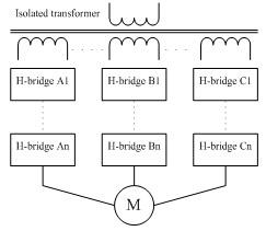
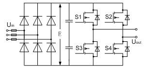
The unit cascaded high-voltage inverter employs multiple cascaded low-voltage power units for direct high-voltage output with structure outlined in Figure 1. The H bridges, see Figure 1, are multi-isolation transformers with a primary side for high-voltage input and a secondary for isolated low-voltage output to individual power units. Each of the system's three phases features one three-phase input and a one-phase output AC-DC-AC inverter of unified structure. See Figure 2 for the structure of the power unit.

Figure 1: Structure of unit cascaded inverter
Figure 2: Structure of power unit

The power unit is powered by one secondary winding of the input transformer. The power units and secondary windings are insulated from themselves and each other. When cascaded in six units for each phase then each unit is subject to the total output current but 1/6 of the output phase voltage and 1/18 of the output power. For a 6KV motor system the output voltage and frequency of each unit can be individually regulated in the range of 0~590V and 0~50Hz for inverter control.


The power unit of a cascaded high-voltage inverter employs carrier phase shift PWM control technology. The inverters shown in Figure 1 are modulated by n-pairs of triangle carriers phase shifting 60o/n in sequence against the fundamental voltage. A 2*n+1 levels of hierarchical phase voltage wave can be generated by stacking up a total of n of each signals modulated by A-phase base carrier control n pieces of power units, A1��An. This is equivalent to a 6*n pulse frequency conversion which offsets all the harmonics below 6*n-1 and leads to total voltage and current distortion as low as around 1%. This can certainly be considered a perfect harmonic free inverter. Power units in one phase of the inverter output the same fundamental voltage. By cascading carriers of each unit at equally staggered phases, then a 12KHz equivalent output phase voltage switch frequency can be acquired by cascading 6 power units, with IGBT switch frequency at 1KHz, from each phase. Power units with low switch frequency reduce switch loss while high equivalent switch output frequency and multiple levels improves output waveform significantly. Better waveforms not only reduce output harmonics but also reduce noise, du/dt value and the motor's torque ripples. All of these enable the inverter to impose no special requirements on motors when applied in speed regulation power. This kind of inverter is suitable for general high-voltage motors without derating and special limits on length of output cables.

Analysis on troubleshooting measures for unit cascaded high-voltage inverter


To ensure the unit cascaded inverter keeps running even with some failed power units for enhanced reliability, it is common to mask off the failed unit together with running modules in the other two phases to maintain the balanced operation of the inverter. This leads to wasted capacity of two units in normal condition and reduced maximum output capacity. However, this approach enjoys the merit of simplicity in theory and maturity in technology.


Neutral point shift (NPS) technology may be used to improve output performance of a multi-level inverter by making the most of the remaining normally functioning units. The neutral point of an inverter is floating and not connected to the center point of load (as shown in commonly available 3-phase motors). This enables the neutral point of an inverter to be away from the load center. Unbalanced three-phase voltage of an inverter's output can change to three-phase balanced load line voltage by regulating the phases of voltage. This regulation measure is equal to exiting a three-phase symmetric line voltage by stacking a zero sequence component to asymmetric output voltage from remaining units in each phase after the failure of some of them. As center points are not connected directly, this line voltage can ensure symmetric and steady operation after symmetric load phase voltage is generated over line voltage load. As the three phases are not symmetric to each other, the conventional optimization control approach of injecting a third harmonic for improved unit voltage utilization rate does not apply any more. The neutral point shift approach does not make the most of system output capacity. In certain system failure cases, the maximum output capacity is even worse than the conventional approach of masking the failed unit and wasting the other two units in the remaining phases.


This document [2] proposed a simple reference wave generation mechanism to replace the sine wave for inverter unit control. It makes the most of output capacity of each unit, improves the total output of the system, and reduces impacts of failures on load without changing current troubleshooting measures. It has the merits of simplicity and ease of use, and can be employed by changing the shapes of reference waveforms in accordance with failure types in the carrier control system and requires little modification to current troubleshooting mechanisms. It requires no shift angle calculation compared with the neutral point shift method.


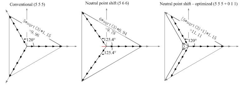
Take the example of a six-unit cascaded system. The troubleshooting methods and output status when one unit in phase A fails are shown in Figure 3.

Figure 3: The three troubleshooting methods

A test system based on LabVIEW and PCI 9846


This study builds a test system with the LabVIEW virtual instrument software platform and ADLINK PCI 9846 high-speed digitizer to verify output performance of cascaded inverters under the three troubleshooting measures described above. The LabVIEW features graphic system design concepts and unique parallel data flow characteristics, and has merits in console interface creation, troubleshooting method design, signal collection and voltage signal performance analysis. As the equivalent output phase voltage switch frequency of cascaded inverters are multiple times that of individual switch devices, and as output voltage harmonics are concentrated in higher bands, it mandates better sampling rates provided by data gathering devices for analyzing inverter output characteristics. Normal data gathering devices can hardly meet such high sampling demands. The modularized instrument PCI 9846 features high sampling rates, up to 40MHz, with precision and good compatibility. With four embedded high-linearity 16-bit high precision A/D and four channels for concurrent sampling the PCI 9846 is ideal for the collection and processing of 3-phase output high frequency signals from cascaded inverters. The LabVIEW drivers provided by ADLINK reduces system development cycles as there are almost no compatibility issues.


See Figure 4 for block diagram of a cascaded inverter's output characteristics test system based on the LabVIEW virtual instrument software platform and ADLINK PCI 9846 digitizer.

Figure 4: The test system block diagram

The said system used a PC to code control solutions and generate corresponding control signals in the LabVIEW virtual instrument platform, according to the three troubleshooting mechanisms described above. The control signals generated by the switch devices then send the data output device to the signal conditioning circuit for processing and transferral to the experiment cascaded inverter. The output signals from the inverter are then sent to the PCI 9846 via the sensors and collected by the data capturing programs in LabVIEW for high-speed collection and storage. The LabVIEW analysis software then analyzes collected signals to finish the cycle of characteristics analysis for output from the cascaded inverter.

Signal collection and analysis results


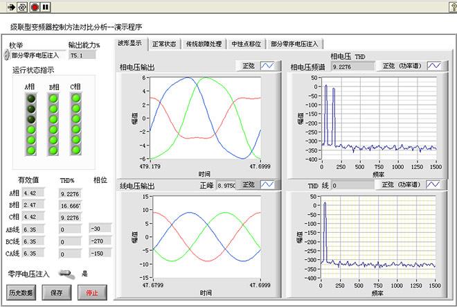
See Figure 5 for the console menu of the test system's LabVIEW virtual instrument platform. A sample analysis on a six-unit cascaded system is presented here along with reference waveforms derived from different troubleshooting mechanisms. See below for a review on the reference waveform equivalent phase voltage and the derived equivalent line voltage waveforms.

Figure 5: The main menu of the test system

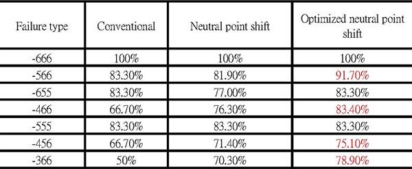
Three troubleshooting mechanisms are used in the demo program with brief descriptions on working theories in each option tab. The indicator lights to the left suggest operation status of a six-unit cascaded inverter. An off indicator means a failed and masked unit. The operation status of three failed units in Phase A is shown in Figure 5. The system output capacity can be seen on top of the indicator lights. It shows that the system maintains near 75% output capacity in case of three failed units in Phase A with an optimized regulation method of injecting partial zero sequence voltage. This is much better than the 50% output capacity of the conventional system. Output from unified effective phase and line voltages, total harmonic distortion of phase voltages, and phases of 3-phase line voltages are displayed in a frame below indicator lights. The option tab to the right provides 3-phase phase voltages, output waveforms of line voltage, and harmonic analysis for one phase of the three. The zero-sequence voltage injection method is available for improved system output capacity by better DC voltage use. The operation results suggest that the proposed troubleshooting method masks failed units only. This leads to asymmetric phase voltages. However, the line voltage output retains equal amplitude and three phase balance and without a third harmonic component by regulating by regulating amplitudes and phases according to types of failures.


Output performances under various types of failures can be seen in Table 1. The Failure Type column gives the total number of normal units left in each of the three phases, e.g. (466) indicates that there are 4, 6, and 6 units working in phase A, B, and C respectively. That is, 2 units in phase A have failed. The maximum output capacity under each troubleshooting method is 66.70%, 76.30%, and 83.40%. respectively. It is clear now that the optimized neutral point shift with partial zero sequence voltage injection troubleshooting method gives the maximum system output for almost every failure type.

Table 1: Output performances by different troubleshooting methods

This study compared three troubleshooting measures in handling failures of cascaded inverters. An output characteristics test system for six-unit cascaded inverter has been built with the LabVIEW virtual instrument software platform and the ADLINK PCI 9846 high speed digitizer for testing and analyzing the effects of three different troubleshooting measures, including quality benchmarks of amplitude, frequency, total harmonic content, and phases of the three-phase voltage. The optimized neutral point shift with partial zero sequence voltage injection troubleshooting method proves a better troubleshooting mechanism for cascaded inverters as it gives the maximum system output and improves fault tolerance.


Related ADLINK Links:
  • More about ADLINK Digitizers
  • More about PCI-9816/9826/9846
Automatic Solar Cell Test Apparatus with Simultaneous-Sampling DAQ Modules 回列表 Application of High-speed Digital Instruments in Testing Firework Products
  • 關於我們
  • 使命與願景
  • 企業永續
  • 投資人關係
  • 新聞與活動
  • 加入凌華
  • 聯絡我們
  • 全球據點
  • 全球經銷商
  • 服務
  • 諮詢技術專家
  • 合作夥伴
  • eRMA服務
  • 關注我們
隱私權政策
Cookie 政策
網站地圖
關於凌華全球據點支援
  •    
  •    
  •    
  •    
Copyright © 2025 ADLINK Technology Inc. All Rights Reserved.
TEL:(03) 216-5088 TEL:(03) 216-5088 FAX:(03) 328-5706 Email:tw@adlinktech.com Address:桃園市龜山區華亞一路66號