-
產品
-
解決方案
邊緣AI

為分散式智慧運算的新一波浪潮注入動能,凌華科技的邊緣AI解決方案提供完整且可擴展的產品組合,涵蓋各層級邊緣運算需求——從低功耗推論到高負載的大型模型推論,皆能靈活部署。每套系統皆採用 AI 整合式設計,內建支援 GPU/加速器的 I/O 介面,實現真正的隨插即用部署。此架構具備 GenAI-ready 優勢,可為視覺 AI、預測分析及裝置端大型語言模型推論提供最佳化效能,加速智慧應用落地。
了解更多娛樂資訊

凌華科技博弈平台解決方案透過我們的軟、硬體和顯示產品為全球遊戲機製造商提供全面性的服務。 我們將電腦專業知識與尖端軟體完美結合,並遵循博弈產業的要求和法規限制來為我們客戶提供服務,使他們能夠專注於打造世界上最好的娛樂體驗。
了解更多智慧醫療

凌華科技專注於醫療可視化設備和經過醫療認證的解決方案,來滿足智慧醫療數位化的需求。 透過PENTA在醫療領域的設計和製造能力,凌華科技的智慧醫療解決方案可加速各種醫療環境中的智慧轉型。
了解更多鐵路

我們的強固設計 CompactPCI、模組化電腦、工業級系統及平板電腦系列產品特別獲選納入車載 ATO/DMI 及軌旁 CTC/RBC/TSR 鐵路解決方案。凌華科技在設計和製造方面的卓越靈活性廣受全球鐵路號誌領導供應商的青睞。
了解更多 -
策略夥伴
AMD-based Solutions
Empower your edge computing with ADLINK, a leading company enabling edge solutions. Leverage AMD's high performance, secure integration, and power efficiency advantages for a wide range of edge, networking, and edge systems with x86 core architecture. Experience superior processing and graphics performance with ADLINK's utilization of AMD EPYC™ Server CPUs and Ryzen™ Embedded series, powered by EPYC™ 9004/9005 Series CPUs and Radeon™ RX, perfect for industrial, medical, automation and gaming applications.
Learn MoreAmpere-based Solutions
Experience the future of edge computing with our comprehensive offering, which includes the Ampere Altra-based COM-HPC module, a developer platform and/or dev kit. Dive in now to unleash superior performance, energy efficiency, and optimized TCO in applications including but not limited to industrial automation, autonomous vehicles, transportation, healthcare, video surveillance, and energy management.
Learn MoreArm-based Solutions
Based on Arm architecture, ADLINK also collaborates with Ampere, NXP, MediaTek, Qualcomm, and Rockchip in module computing development and value-added solutions across varied industries, including smart manufacturing, autonomous driving, robotics, AMR, drone, transportation, logistics, retail, infotainment, healthcare, security, and more.
With plug-and-play tools, development kits, and all-encompassing systems, ADLINK and Arm empowers developers to accelerate and realize their innovations.
Learn MoreIntel-based Solutions
ADLINK is a Prestige Partner of Intel® Partner Alliance. From modular computing to system-ready use cases, ADLINK collaborates closely with Intel to deliver scalable, interoperable solutions that accelerate the deployment of intelligent devices with end-to-end analytics.
ADLINK leverages Intel® AI Edge Systems to deliver scalable, high-performance AI at the edge. Built on proven, benchmarked edge computing platforms, these solutions integrate GPU and NPU acceleration with enterprise-ready manageability to optimize real-world AI workloads. With long lifecycle support, industrial-grade reliability, and best-in-class TCO, ADLINK and Intel enable faster time-to-market and seamless AI deployment across diverse edge environments.
Learn MoreMediaTek-based Solutions
ADLINK Technology and MediaTek are strategic partners that deliver innovative and powerful solutions for edge computing and edge AI applications. Leveraging MediaTek's flagship, power-efficient Genio platform SoCs and ADLINK's expertise in embedded and rugged designs, they provide high-performance, energy-efficient, and reliable modules and platforms in accomplishing various IoT use cases, such as smart home, human-machine interface, multimedia, industrial IoT, and robotics.
Learn MoreNVIDIA-based Solutions
To fulfill industry-specific requirements, ADLINK is able to efficiently develop edge AI platforms, AI smart cameras, medical platforms, and AI portable GPU accelerators based on NVIDIA Jetson modules, the NVIDIA IGX platform, and RTX Embedded GPUs for applicable industries, including smart manufacturing, autonomous driving, autonomous mobile robots (AMR), robotics, transportation, healthcare, logistics, retail, infotainment, AI development, professional graphics, and gaming.
Learn MoreNXP-based Solutions
Utilizing NXP's i.MX 8 and i.MX 9 series technology, ADLINK offers edge-connected solutions to assist medical, test & measurement, automation, and smart city customers reduce TCO. This combination of NXP's technology with ADLINK's R&D experience in edge computing provides versatile and dynamic solutions for critical applications.
Learn MoreQualcomm-based Solutions
Qualcomm Technologies’ portfolio of leading robotics and drones solutions is driving next-generation use cases, including autonomous deliveries, mission critical use cases, commercial and enterprise drone applications and more.
Among them, the Qualcomm QRB5165 solution is designed to help build consumer, enterprise or industrial robots with 5G connectivity, on-device AI and machine learning, superior computing, and intelligent sensing capabilities. By adopting Qualcomm QRB5165, ADLINK’s module will enable the proliferation of 5G in robotics and intelligent systems.
Learn More
-
支援
-
關於我們


- 首頁
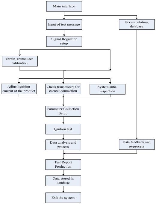
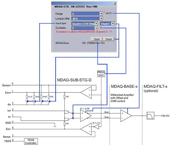
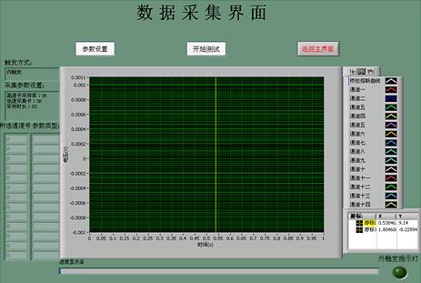
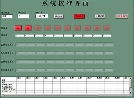
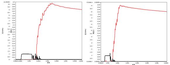
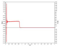
- Application of High-speed Digital Instruments in Testing Firework Products
- 登錄
- home
-
產品
-
解決方案
邊緣AI
為分散式智慧運算的新一波浪潮注入動能,凌華科技的邊緣AI解決方案提供完整且可擴展的產品組合,涵蓋各層級邊緣運算需求——從低功耗推論到高負載的大型模型推論,皆能靈活部署。每套系統皆採用 AI 整合式設計,內建支援 GPU/加速器的 I/O 介面,實現真正的隨插即用部署。此架構具備 GenAI-ready 優勢,可為視覺 AI、預測分析及裝置端大型語言模型推論提供最佳化效能,加速智慧應用落地。
了解更多娛樂資訊
凌華科技博弈平台解決方案透過我們的軟、硬體和顯示產品為全球遊戲機製造商提供全面性的服務。 我們將電腦專業知識與尖端軟體完美結合,並遵循博弈產業的要求和法規限制來為我們客戶提供服務,使他們能夠專注於打造世界上最好的娛樂體驗。
了解更多智慧醫療
凌華科技專注於醫療可視化設備和經過醫療認證的解決方案,來滿足智慧醫療數位化的需求。 透過PENTA在醫療領域的設計和製造能力,凌華科技的智慧醫療解決方案可加速各種醫療環境中的智慧轉型。
了解更多鐵路
我們的強固設計 CompactPCI、模組化電腦、工業級系統及平板電腦系列產品特別獲選納入車載 ATO/DMI 及軌旁 CTC/RBC/TSR 鐵路解決方案。凌華科技在設計和製造方面的卓越靈活性廣受全球鐵路號誌領導供應商的青睞。
了解更多 -
策略夥伴
AMD-based Solutions
Empower your edge computing with ADLINK, a leading company enabling edge solutions. Leverage AMD's high performance, secure integration, and power efficiency advantages for a wide range of edge, networking, and edge systems with x86 core architecture. Experience superior processing and graphics performance with ADLINK's utilization of AMD EPYC™ Server CPUs and Ryzen™ Embedded series, powered by EPYC™ 9004/9005 Series CPUs and Radeon™ RX, perfect for industrial, medical, automation and gaming applications.
Learn MoreAmpere-based Solutions
Experience the future of edge computing with our comprehensive offering, which includes the Ampere Altra-based COM-HPC module, a developer platform and/or dev kit. Dive in now to unleash superior performance, energy efficiency, and optimized TCO in applications including but not limited to industrial automation, autonomous vehicles, transportation, healthcare, video surveillance, and energy management.
Learn MoreArm-based Solutions
Based on Arm architecture, ADLINK also collaborates with Ampere, NXP, MediaTek, Qualcomm, and Rockchip in module computing development and value-added solutions across varied industries, including smart manufacturing, autonomous driving, robotics, AMR, drone, transportation, logistics, retail, infotainment, healthcare, security, and more.
With plug-and-play tools, development kits, and all-encompassing systems, ADLINK and Arm empowers developers to accelerate and realize their innovations.
Learn MoreIntel-based Solutions
ADLINK is a Prestige Partner of Intel® Partner Alliance. From modular computing to system-ready use cases, ADLINK collaborates closely with Intel to deliver scalable, interoperable solutions that accelerate the deployment of intelligent devices with end-to-end analytics.
ADLINK leverages Intel® AI Edge Systems to deliver scalable, high-performance AI at the edge. Built on proven, benchmarked edge computing platforms, these solutions integrate GPU and NPU acceleration with enterprise-ready manageability to optimize real-world AI workloads. With long lifecycle support, industrial-grade reliability, and best-in-class TCO, ADLINK and Intel enable faster time-to-market and seamless AI deployment across diverse edge environments.
Learn MoreMediaTek-based Solutions
ADLINK Technology and MediaTek are strategic partners that deliver innovative and powerful solutions for edge computing and edge AI applications. Leveraging MediaTek's flagship, power-efficient Genio platform SoCs and ADLINK's expertise in embedded and rugged designs, they provide high-performance, energy-efficient, and reliable modules and platforms in accomplishing various IoT use cases, such as smart home, human-machine interface, multimedia, industrial IoT, and robotics.
Learn MoreNVIDIA-based Solutions
To fulfill industry-specific requirements, ADLINK is able to efficiently develop edge AI platforms, AI smart cameras, medical platforms, and AI portable GPU accelerators based on NVIDIA Jetson modules, the NVIDIA IGX platform, and RTX Embedded GPUs for applicable industries, including smart manufacturing, autonomous driving, autonomous mobile robots (AMR), robotics, transportation, healthcare, logistics, retail, infotainment, AI development, professional graphics, and gaming.
Learn MoreNXP-based Solutions
Utilizing NXP's i.MX 8 and i.MX 9 series technology, ADLINK offers edge-connected solutions to assist medical, test & measurement, automation, and smart city customers reduce TCO. This combination of NXP's technology with ADLINK's R&D experience in edge computing provides versatile and dynamic solutions for critical applications.
Learn MoreQualcomm-based Solutions
Qualcomm Technologies’ portfolio of leading robotics and drones solutions is driving next-generation use cases, including autonomous deliveries, mission critical use cases, commercial and enterprise drone applications and more.
Among them, the Qualcomm QRB5165 solution is designed to help build consumer, enterprise or industrial robots with 5G connectivity, on-device AI and machine learning, superior computing, and intelligent sensing capabilities. By adopting Qualcomm QRB5165, ADLINK’s module will enable the proliferation of 5G in robotics and intelligent systems.
Learn More
-
支援
-
關於我們