Simon You,
ADLINK Technology
Most discussions on motion controllers center on tools and planning for large numbers of trajectories and control theories. However, the recent rapid advancement of semiconductor and opto-electronic industries has led to increased production equipment needs. Traditional production equipment can be classified as factory automation (FA) and uses PLC controllers to control production flow. Such applications do not meet the productivity requirements and highly complex needs of the modern semiconductor and opto-electronic equipment.
As the number of axes increases and control methods become more complex, equipment motion requirements cannot consist of simple switches or program controls. These control applications will typically use a database, internet connection, and image inspection systems. Motion is mapped out by external variables that must perform accurate positions and high-speed motion. These complex functions must be architected and executed under multi-thread programs. Older PLC controllers are unsuitable for these applications, hence the move away from machinery and electric control to machine automation (MA), which is gradually becoming the norm. PLC systems are also gradually being replaced by PC-based hardware and software. This article discusses commonly used functions using SSCNET for semiconductor and opto-electronic industries.
SSCNET Controller Architecture
SSCNET is a protocol specifically designed for motion control by Mitsubishi Electric. The first generation architecture was developed in the 1990s. The latest generation (SSCNET III) utilizes a fiber optic system combined with a high-performance servo driver (J3B). The highly successful first and second generation serial motion control technology is already controlling over two million axes on the market today. SSCNET's principles are not very complicated, its architecture consisting of four levels as shown in Figure 1. According to the SSCNET specification, every T represents 0.888ms and can control six axes. However, with the currently available ADLINK SSCNET motion card, 12 axes can be controlled in the same amount of time during a given cycle.
1. Motor Control Layer:
Built into Mitsubishi B-type servo drivers. Maintains Mitsubishi's servo control technology, but adds a communication interface with a fixed clock to receive commands and report servo status, in addition to controlling motor position, speed, and torque. A Station ID switch can be used to set axis numbers instead of relying on wiring order.
2. Network Communication Layer:
This technology primarily consists of all the axes on a network moving in a fixed control cycle. In other words, control is characterized by multi-axis isochronism and is able to achieve absolute synchronization over multiple axes. Communication is carried out with a Master/Slave configuration. The Master IC is typically the main control host and the Slave IC is embedded in the servo driver. The Master IC is responsible for issuing commands to each axis during a control cycle and receiving information sent by each Slave IC. The synchronized clock cycle is 0.888ms.
3. Motion Control Layer:
This layer must have a motion control system synched to SSCNET. It is responsible for sending commands to the SSCNET Master IC and retrieving information on each axis from the Master IC. Implementing this control system on a PC can be done in one of two ways. The first method is to use a microprocessor to receive control cycle interrupts from the Master IC and to calculate motion commands that are sent to the Master IC within the fixed time of the cycle. It also has to read Master IC information at the same time. This microprocessor is independent of the PC and is typically designed as part of the cycle control card. ADLINK's PCI-8372 uses a TI floating-point operation DSP. The second method is to use the PC's CPU to capture Master IC control cycle interrupts. Similarly, it must calculate motion commands that are sent to the Master IC within the fixed time cycle. SSCNET-N601, developed by the Mechanical Industry Research Laboratories of the Industrial Technology Research Institute, uses a VenturCom RTX development environment. Benefits of the first method include stability and convenience of use for system designers. Benefits of the second method include direct control over SSCNET for system designers, however synchronization issues must be considered.
4. User Interface Layer:
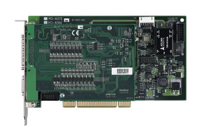
This layer is purely software-based and is typically closely tied to the motion control layer. This layer is extremely important for the commercialization of SSCNET control cards because the end user (equipment manufacturer) must use the controller card's interface functions or graphical control components in designing the system's production sequence. Semiconductor and opto-electronics equipment are low volume yet have highly varied requirements- suitable for the majority of equipment software developers who prefer a user-friendly interface. Tools and production machines are high volume yet have a limited range of requirements- ideal for few users who prefer working with the motion control layer. The majority of such users have a background in scientific theory, or are already skilled in using the motion control interface. In such cases, the motion control card becomes an interface. Most users only understand the core principles in production methods and merely use general or specific functions developed by the manufacturer to simplify equipment design. All they require is product reliability; extensive knowledge of motion control theories is not necessary. The user interface layer in Figure 1 shows that user commands need not be in synch with SSCNET communication cycles. This reduces the complexity of equipment design. The following section is based on ADLINK's PCI-8372 SSCNET 12 axis controller (Figure 2) to introduce commonly used functions in today's semiconductor and opto-electronics manufacturing equipment.
General Semiconductor and Opto-Electronics Equipment Functionality
1. Load/Unload Systems
Load/unload functions are commonly seen in semiconductor equipment to replace the loading and unloading work of operators. Loading/unloading is typically accomplished with a single axis. If the system uses loading and unloading in several locations, single axis commands can be called at the same time, or total axis concurrent movement command can also be used. Designers can send commands based on desired position and speed and wait for the position signal. Load/unload systems focus on stability and ease-of-use.
2. Pick and Place Systems
Pick and place motions may be used on both packaged chips or sliced wafers. Most systems implement pick and place with vacuum suction and two axes. Motions include pick, raise, planar movement, lower, and place, which can be combined with image detection, or input spot checking, or even position comparisons. Using ADLINK SSCNET offers smooth turning points between these five motions, reducing vibration and improving stability. With a DPS handling the entire movement, extra motions can be inserted to provide better real-time capabilities. Pick and place systems rely on cycle speeds--the faster the better (for most cases). Bottlenecks can include the speed of image detection and unsmooth motion.
3. Die Bonding System
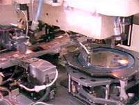
During a die bonding process, a multi-stage continuous velocity profile is necessary. It is a roundtrip motion, during which an adjustment is made for bonding time. During this process, chip angles, other I/O point alignment, etc. must be corrected based on image test results. Low-level machines are unable to correct motion angles, typically coming to a complete stop before bonding, correcting the angle, and then performing the bond. ADLINK's SSCNET can correct angles while in motion via feedback from imaging data for continuous bonding.
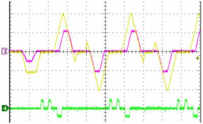
Cycle speed is vital in accomplishing continuous bonding-the higher the speed the better. Knowledge of bonding and motion smoothness are also key factors in achieving optimal performance. The die bond machines shown in Figure 3 picks chips from the wafer on the right and places it on the lead frame to the left. A continuous velocity profile can be used for a flip chip bonder. Figure 4 is a bonding velocity chart of a bonder with built-in dynamic position correction.
4. Wire Bonding Systems
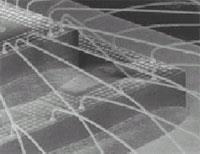
The process of wire bonding is more complex than that of die bonding, requiring more than two axes for three dimensional space movements. This process also relies on a multi-stage continuous velocity profile, with the last stage typically a binding or breaking motion. The results of the wire bonding process are shown in Figure 5. ADLINK's SSCNET can switch to velocity and torque modes in mid-motion. For precise wire bonds, image comparison accuracy is not necessary. All that is required is that routing between wire bond start and end points, and velocity be programmed. With SSCNET's nano-scale precision (131,072 resolution degree motor), wire bond precision is easily accomplished as long as motion control velocity, precision, and wire shape are consistent.
5. Laser repair for TFT-LCD system
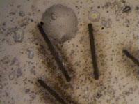
Similarly, laser repair for TFT-LCD equipment also requires highly precise motion control. Each area requiring repair is marked with several short lines, relying on the precision and speed of the laser. ADLINK's SSCNET high-precision positioning and control command synchronization is capable of producing the necessary precise lines. Figure 6 shows the test results of an SSCNET-equipped repair system.
6. IC inspection by continuous on-the-fly camera trigger
Most QFP and BGA packaged ICs come out of manufacturing on a tray. Visual inspection requires a vision system matched with a motion control system. ADLINK's SSCNET provides a dynamic position comparator that simultaneously outputs trigger signals to image grabbers. Dynamic image testing improves manufacturing capability. This type of application can also be applied to AOI systems. During the process of image scanning, such systems can dynamically adjust the distance between components being tested for high-speed synchronized triggers and real-time position correction.
7. Common working area crash prevention by interlock function
It's also common to have dual control systems in the same work area that may cross paths. A "traffic light" is necessary to avoid collisions, which is typically controlled by system design. This resulted in lower productivity or even collisions due to mistimed responses. ADLINK's SSCNET provides a crash-proof mechanism via a single command for such an environment. This command works by slowing down the axis that is lagging behind to allow for proper clearance in the area of intersection.
8. TFT-LCD carrying by gantry mode
Gantry mode can be used to move heavy objects, such as large LCD panels. This mode is easily carried out with ADLINK's SSCNET. Since all axes can move simultaneously with absolute positioning commands by simultaneously sending commands to two axes, in principle, this will allow them to move simultaneously in the same cycle. For practical purposes, simply configure both axes as a gantry mode relationship and the commands need only be sent to the main axis.
Conclusion
SSCNET is the latest motion control technology with all the advantages of traditional motion control systems, yet offering simpler automated design thresholds for equipment developers. With a well though out user interface, SSCNET offers the ultimate development experience.
Reference
[1] Yi-Tun Huang, "PC-Based SSCNET Motion Control Systems and Development Trends", Mechanical Industry Journal, pp. 247-253, September 2003.
[2] Chung-Wei Cheng, Hsin-Sheng Yang, Chie-Ding Tseng, Wen-Peng Tseng, "Research on PC-Based Motion Control Network Controllers", Mechanical Industry Journal, pp. 173-185, February 2005.