Mechanical Computer Vision Applications - Key Punch Image Location System Design
Daniel Lian,
ADLINK Technology
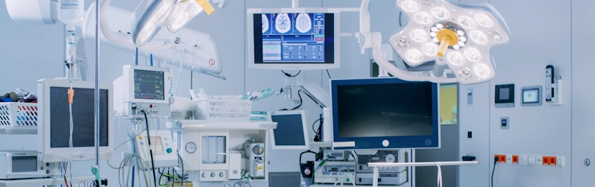
Most computer vision applications can be separated into four categories: location, measurement, decode, and defect inspection. Location applications are already widespread; and mechanical vision systems also encompass a wide variety of functions, such as inspecting components of a motherboard. Mechanical vision can also be used to control robot. Installing a CCD on an robot and using vision to identify location can drive the use of robots in high-risk medical research, such as virus research and pharmaceutical mixtures. Robots are not only very precise, but provide a safe method to perform such research.
Coordinate Transform after Vision Location
There are many vision comparator libraries available on the market. Users simply need to select the library that best fits their needs. The system used in this article is the eVision EasyMatch, a grayscale-dependant image matching library developed by Euresys. It offers excellence response speed and can achieve sub-pixel precision matching. Rotation, scale change (shrink/expand), and translation can accurately find golden image location. This article discusses the two-dimensional coordinate "shift" and "rotation" produced after image location.
Coordinate Shift and Rotation
If shift and rotation occurs at the same time, first calculate shift and then use the rotation function for accurate results.
System Architecture
This system introduces a way to design an automated location system that integrates mechanical motion and computer vision.
Basic Architecture
- GEME-3000 Controller: Includes an HSL controller card and comes installed with Windows® XP OS.
- 3-Axis motion Platform: Mitsubishi servo motors and linear stages
- Motion Controller: HSL-4XMO controller module
- Vision Components: IEEE1394 CCD, Euresys eVision EasyMatch for pattern matching and to calculate shift compensation
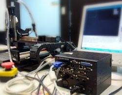
Figure 1: System Architecture
System Process
This system introduces a way to design an automated location system that integrates motion and vision.
System Calibration
- Mitsubishi driver calibration: 10,000 pulse/roll
- Linear stage pitch vs. Motor pulse/roll:
Example: Linear stage pitch = 10 mm/roll, 10,000 pulse/roll = 1 um/pulse
- Choosing a Field of View (FOV): The FOV should be larger than the size of the location mark. Too small: the receivable initial location tolerance becomes small. Too large: the location image is too big and thus the image location is very inaccurate.
- Selecting the working distance of CCD: The working distance needs to be greater than the perforated-table in order to prevent it from colliding with the camera during focusing. Once the FOV and working distance are determined, select a lens and extension ring.
Instruction
- Start the system's three axes will return the home position of stage. After location, manually place parts on each axis location platform and perform the initial movement.
- Manually control the Z-axis to slow it down and move it close to the top of the platform (~0.5-1.0 mm).
- Manually control the X/Y axes to place the perforated-table exactly above the first hole of the component. Use the Z axis to slowly move it down to punch through the first hole. If the location is not accurate, manually move the perforated-table to a more precise position.
- Once accurately position, use the Z axis to raise the CCD so the image shows the entire location. Execute the flowchart below.
Automated Location
- Initialize the position on the component manually placed on the 3-axis location platform and start the system.
- The system will drive the 3-axis platform to move the CCD above the location (two different locations). The image will be captured and find the "golden image" position.
- Calculate the shift X/Y and rotation angle of the "initial position".
- Re-calculate the point table of the holes on the perforated-table by transforming to polar coordinates.
Conclusion
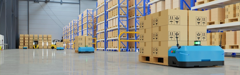
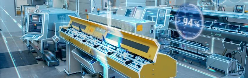
Mechanical vision system applications not only improve manufacturing capacity, but also increase user capability. Mechanical vision systems are ideal for the following fields:
- Jobs needing a microscope or magnifier. Long term use of magnifying equipment can be harmful to operators and result in inconsistent results.
- Hazardous work environments: high or low temperatures, vacuums, high pressure, loudness, high radiation, high voltage or current, etc.
- Repeatable work. Continually performing the same job can wear out operators, leading to neglect and harm, or poor performance. Mechanical vision can be used 24 hours a day and can perform high-speed inspections. Vision accuracy can also be constrained to a specific degree.
- Applications needing quick processing: military weapon control or real-time, high-quantity production lines.
- High precision work: measurement, position, item differentiation.
Reference Materials
[1] ADLINK PMC-7852 user manual
[2] ADLINK HSL-4XMO user manual
[3] Euresys eVision user manual