By Jeff Munch,
CTO, ADLINK Technology
According to Intel, there are currently one billion embedded intelligent systems in existence. As this statistic relates to the transportation industry, the worldwide market for intelligent transportation systems (ITS) devices is expected to increase at a 22.2% compound annual growth rate (CAGR) and reach a value of $65 billion in 2015 (Source: BCC Research's 2010 Intelligent Transportation Systems Review).
Intelligent transportation systems enable users to be better informed and make safer and smarter use of transport networks. They also allow transport providers to better track and manage their critical assets. However, designing an embedded solution with intelligence adds complexity to an already challenging development environment. Ruggedization, regulatory requirements and/or certification, size, and cost constraints mean that embedded ITS systems will by definition be a mix of all of these starting from an existing small form factor (SFF) such as COM, COM Express, EBX, or a variation.
ITS Design Requirements: Rugged, Small, Certified
Transportation solutions are most often housed outdoors or in moving vehicles, where exposure to a variety of climates dictates the need to operate in extended temperatures and to support the extremes of shock, vibration and humidity. In addition, space restrictions require putting expanding functionality on ever-smaller board form factors. Because of cost and the complex nature of intelligent embedded computing solutions for transportation, system qualification can take a very long time and require designers to look for products with a long lifecycle. Finally, transportation infrastructure is highly regulated around the world, so extra certification requirements are almost always part of a rugged ITS specification.
There is no panacea for the challenges that are inherent in the variety of rugged, horizontal applications for ITS, but rather there are optimal solutions that can provide the highest level of success based on the specific application requirements. We'll examine some systems and uncover the tradeoffs reached to achieve optimal results using COTS SFFs.
Locomotive DVR & Data Gateway
A leading global supplier of technology solutions for railroads wanted to develop an onboard locomotive video/audio capture system to aid in accident investigations and provide safety training to crews. In addition to video and audio recording, requirements for the system included remote monitoring and control, real-time health monitoring and wireless video download.
To address vibration issues with data storage, the system incorporated solid-state media in a sealed, tamper-resistant housing. General options for storage include rotating hard disk drives (HDDs) for economy or solid-state drives (SSDs), which are more rugged, but also come at a higher price point. HDDs contain spinning disks and movable read/write heads, whereas SSDs use microchips that retain data in non-volatile memory chips and contain no moving parts, making them less susceptible to physical shock, altitude, and vibration issues. SSDs have faster access time and lower latency than do HDDs, and the flash memory and circuit board materials of SSDs make them lighter than higher performing HDDs. With the weight and vibration resistant requirements of mobile applications, solid-state media is a better choice for most ITS solutions.
For the onboard locomotive video/audio capture system, designers created a rugged solution around the Intel embedded architecture and Embedded Board eXpandable (EBX) Single Board Computer (SBC) form factor. EBX is a good format options for designs that can handle a slightly larger (than, say, a computer-on-module) single-board computer (SBC) form factor. Still small with just 46 square inches of surface area (8" x 5.75"), EBX balances size and functionality with a bolt-down SBC format supporting rugged embedded designs with higher-performance CPUs such as those using multicore technology for networking, digital signal processing (DSP) and graphics-heavy applications, and generous on-board Input/Output (I/O) functions to support everything from large data exchange to video. The design accommodated both functionality and rugged requirements for the train system with dual Ethernet, CRT and flat panel video, multiple serial and USB ports, SATA and IDE interfaces, high-definition audio, and General Purpose Input/Output (GPIO) support.
A critical byproduct of on-site video/audio capture is reduced litigation and settlement costs due to accurate incident reporting. System reliability is critical to users in terms of return on investment, so designers used products that provided documented uptime in their specifications and met the Electromagnetic Interface/Compatibility (EMI/EMC) EN50155 industry standard.
Intelligent Bus Network
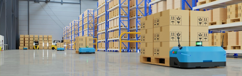
A leading designer of innovative technology solutions for all modes of public transportation implemented an on-board smart system enabling transit agencies to communicate with customers and dispatch, maintain its fleet and collect and analyze operating data (Figure 1).The numerous control inputs included vehicle run switch, front and rear door, wheelchair ramp, stop request, odometer and emergency alarm. The solution also required GPS with driving recorder and support for both wireless and cellular transmission. Finally, the company required a Class A device for testing against SAE International standards.
Figure 1: The hardware for the intelligent bus network solution was housed in a fixed space near the floor of each fleet vehicle, making the use of a rugged, small form factor design a must to compensate for space restrictions and potential shock, vibration and temperature extremes. (Image courtesy of U.S. Department of Transportation.)
Due to both space constraints within transit vehicles and the highly specialized application requirements, the COM Express form factor was selected for this particular embedded solution. Computer-on-modules (COMs) are complete embedded computers built on a single circuit board for use in small or specialized applications requiring low power consumption or small physical size. Though they are compact (ETX/XTX at 114 x 95 mm and COM Express at 125 x 95 mm to 84×55 mm) and highly integrated, COMs can accommodate complex CPUs.
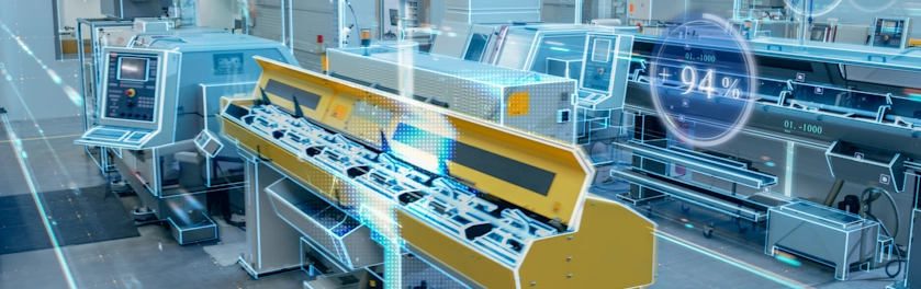
With the COM approach, all generic PC functions are readily available in an off-the-shelf foundation module, allowing system developers to focus on their core competencies and the unique functions of their systems. A custom designed carrier board complements the COM with additional functionality that is required for specific applications. The carrier board provides all the interface connectors for peripherals, such as storage, Ethernet, keyboard/mouse and display. This modularity allows the designer to upgrade the COM on the carrier board without changing any other board design features, and also allows more customization of peripherals as dictated by a specific application (Figure 2).
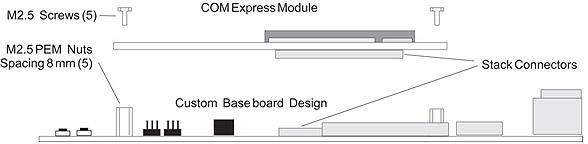
Figure 2: A design using the COM Express form factor provides off-the-shelf functionality and an easy upgrade path by putting the customization on the baseboard, thereby creating more flexibility with the module without sacrificing performance.
The COM Express form factor offers flexibility in the development and advancement of ultra-rugged embedded transportation applications. By using the modular processing block, the designer creates a price and value advantage; he/she isn't locked into a single vendor for board creation and can customize based on pricing and performance requirements. Because it is easily swapped from a carrier board and comes in one of the smallest form factors, COM Express is ideal for long-life embedded applications with a critical development cycle, as well as more progressive applications that require frequent processor upgrades without affecting other application design elements.
The complete solution to create the intelligent bus network consisted of a rugged COM Express module plus custom baseboard with an Intel Atom processor. Mini PCI Express slots support 802.11 a/b/g/n and cellular modems for connectivity and specified operating and storage temperature, shock and operating and non-operating vibration requirements were all designed into and extensively tested to create the custom solution.
Train Operator Display
A leading provider of technology solutions in transportation, aerospace, defense and security was creating an in-vehicle operator display system that could be installed in rail networks across the globe. The purpose of the display system was to provide an interface for conductors to monitor and manage train activity. Because the display system was being designed for subway and rail systems in multiple countries, the solution needed to account for variation: multiple sizes for display installation areas; multiple power requirements; multiple certification requirements.
The end solution started with two customized panel sizes, 10" and 6.5", with Texas Instruments ARM-based processors (Figure 3).The "system on display" style rugged panels offered low power consumption, which allowed a slim, fanless design and the ability to fit into tighter spaces. Two power supplies were included to meet international standards (input voltage 24VDC/36VDC or 72VDC/110VDC), and the solution was built in accordance with transportation specifications from Cenelec, the European Committee for Electrotechnical Standardization, and Arema, the American Railway Engineering and Maintenance-of-Way Association.
Figure 3: The customized panel is a System on Display combining an LCD panel, CPU board and touch-screen in a compact package that can be used in both industrial and consumer-based applications, such as point-of-sale kiosks and digital advertising signage.
This display system was also designed to meet a stringent mean time between failure (MTBF) requirement of over 100,000 hours (~ 2x normal MTBF requirement). To accomplish this, the design had to be rugged, The initial step was to select a rugged board that was designed for harsh environments from the ground up. With rugged—as opposed to ruggedized—solutions that support the extremes of shock, vibration, humidity and temperature, care is given to component selection, circuit design, Printed Circuit Board (PCB) layout and materials, thermal solutions, enclosure design and manufacturing process.
Robust test methods ensure optimal product design phases in order to meet a product's stringent requirements, such as -40 °C to +85 °C operating temperature range, MIL-STD, shock and vibration and long-term reliability. In the end, the designers selected hardware certified to meet military standard MIL-HDBK-217F for temperature range and EN61373 Class 1B / Arema Class for shock and vibration, as well as EMI/EMC: EN 610000-6-4 / EN 61000-6-2 / EN50121.
Meeting the ITS Design Challenge
As exemplified in the previous ITS designs, consistent requirements included the need for extreme environmental standards, space restrictions and specialized certifications to meet both technical and regulatory standards. To overcome these challenges, developers utilized already proven rugged hardware to provide a solid foundation for their designs. In addition, a familiarity with the pros and cons of small form factor options helped them to create a baseboard design that could best accommodate size and performance requirements. And to ensure certification success and system longevity, designers created solutions around standards-based hardware and products that follow the roadmap of an established architecture.
© Extension Media, 2013. This is the author's version of the work. It is posted here by permission of Extension Media for your personal use. Not for redistribution. The definitive version was published in EECatalog.com, February 19, 2013, http://www.extensionmedia.com/"