• 購物車(0)
繁體中文
English
简体中文
한국어
日本語
繁體中文
  • 登錄
  • 產品
    嵌入式模組化電腦
    • COM-HPC
    • COM Express
    • OSM
    • SMARC
    • Qseven
    • ETX
    GPU解決方案
    • MXM GPU 模組
    • PCIe 顯示卡
    強固型運算
    • CompactPCI & CompactPCI Serial
    • VPX
    • PC104
    • AVA Railway Rugged Computers
    • PIDS
    邊緣運算平台
    • 工業電腦 / 主機板 / 單板電腦
    • 嵌入式電腦 / IoT Gateway
    • 邊緣 AI 運算平台
    • AI 智慧相機
    • 機器人控制器
    • 工業級固態硬碟 (SSD)
    工業級顯示系統與平板電腦
    • 工業級觸控顯示器
    • Open Frame 平板電腦
    • All-in-One 平板電腦
    • 強固型面板電腦
    • 數位看板播放器
    車用解決方案
    • 自動駕駛解決方案
    • AI-ADAS 解決方案
    網路通訊與伺服器
    • AI GPU 伺服器
    • 工業級邊緣伺服器
    • 網路安全平台
    • P5G 工業自動化專網-MicroRAN
    自動化與控制
    • 機器視覺
    • 運動控制與 I/O
    • EtherCAT 運動控制解決方案
    • HMI 平板電腦
    • 資料擷取模組
    • GPIB 與數字化儀
    • PXI 平台與模組
    • 自主移動機器人
    • 工業物聯網閘道器
    設計與製造服務
    • DMS+ (ODM/OEM 服務)
    醫療專用電腦與顯示器
    • 醫療專用觸控電腦
    • 醫療專用顯示器
    • 醫療專用 BOX PC
    軟體
    • EdgeGO
  • 產業
    車用解決方案 軍工與航太 娛樂資訊 智慧醫療 半導體解決方案 智慧製造 鐵路 機器人技術

    車用解決方案

    車用解決方案

    凌華科技的自動駕駛運算平台採用尖端技術,致力提供更安全、更高效的駕駛運行。以強大的運算能力,滿足自動駕駛和先進駕駛輔助系統(ADAS)技術,並提供適用於汽車的堅固設計。

    了解更多

    軍工與航太

    軍工與航太

    在軍工航太領域中,準確觀察環境並做出快速可靠的決策並及時採取行動至關重要。 凌華科技強固的系統和Data Distribution Service(DDS)是大型數據基礎架構的關鍵,該基礎架構可收集、儲存、分析資訊並將資訊從現場傳遞給決策者。

    了解更多

    娛樂資訊

    娛樂

    凌華科技博弈平台解決方案透過我們的軟、硬體和顯示產品為全球遊戲機製造商提供全面性的服務。 我們將電腦專業知識與尖端軟體完美結合,並遵循博弈產業的要求和法規限制來為我們客戶提供服務,使他們能夠專注於打造世界上最好的娛樂體驗。

    了解更多

    智慧醫療

    智慧醫療

    凌華科技專注於醫療可視化設備和經過醫療認證的解決方案,來滿足智慧醫療數位化的需求。 透過PENTA在醫療領域的設計和製造能力,凌華科技的智慧醫療解決方案可加速各種醫療環境中的智慧轉型。

    了解更多

    半導體解決方案

    半導體解決方案

    你所能想像的一切,都因晶片而有所改變。為了滿足不同應用的需求,完美的晶圓製造對於品質的工藝要求到效率和生產力的過程都無比講究。

    了解更多

    智慧製造

    智慧製造

    借由邊緣運算,ADLINK 智慧製造解決方案加速更快的數據決策,為半導體和電子製造業創造更具彈性和安全性的生產環境。

    了解更多

    鐵路

    鐵路

    我們的強固設計 CompactPCI、模組化電腦、工業級系統及平板電腦系列產品特別獲選納入車載 ATO/DMI 及軌旁 CTC/RBC/TSR 鐵路解決方案。凌華科技在設計和製造方面的卓越靈活性廣受全球鐵路號誌領導供應商的青睞。

    了解更多

    機器人技術

    機器人技術

    自主移動機器人(AMR)能夠在沒有或最低限度的人工操作監督之下來執行工作。在一些可以使用大量的AMR設施譬如學校、醫院、大型購物中心和工廠之類的,以提高營運效率和生活品質。

    了解更多
  • 策略夥伴
    AMD Ampere Arm Intel MediaTek NVIDIA NXP Qualcomm

    AMD-based Solutions

    AMD-based Solutions by ADLINK

    Empower your edge computing with ADLINK, a leading company enabling edge solutions. Leverage AMD's high performance, secure integration, and power efficiency advantages for a wide range of edge, networking, and edge systems with x86 core architecture. Experience superior processing and graphics performance with ADLINK's utilization of AMD Ryzen™ Embedded series, powered by Radeon™ RX, perfect for industrial, medical, automation and gaming applications.

    Learn More

    Ampere-based Solutions

    Ampere-based Solutions by ADLINK

    Experience the future of edge computing with our comprehensive offering, which includes the Ampere Altra-based COM-HPC module, a developer platform and/or dev kit. Dive in now to unleash superior performance, energy efficiency, and optimized TCO in applications including but not limited to industrial automation, autonomous vehicles, transportation, healthcare, video surveillance, and energy management.

    Learn More

    Arm-based Solutions

    Arm-based Solutions by ADLINK

    Based on Arm architecture, ADLINK also collaborates with Ampere, NXP, MediaTek, Qualcomm, and Rockchip in module computing development and value-added solutions across varied industries, including smart manufacturing, autonomous driving, robotics, AMR, drone, transportation, logistics, retail, infotainment, healthcare, security, and more.

    With plug-and-play tools, development kits, and all-encompassing systems, ADLINK and Arm empowers developers to accelerate and realize their innovations.

    Learn More

    Intel-based Solutions

    Intel based Solutions by ADLINK

    ADLINK is a Titanium member in Intel® Partner Alliance. From modular computing to system-ready use cases, ADLINK works closely with Intel to provide scalable, interoperable solutions that accelerate your intelligent device deployment with end-to-end analytics.

    Utilizing Intel-based modules, ADLINK accelerates your products’ time to market with edge AI platform development support while addressing diverse industry pain points, such as in networking, smart manufacturing, autonomous driving, AMR, transportation, healthcare, retail, and infotainment.

    Learn More

    MediaTek-based Solutions

    MediaTek-based Solutions by ADLINK

    ADLINK Technology and MediaTek are strategic partners that deliver innovative and powerful solutions for edge computing and edge AI applications. Leveraging MediaTek's flagship, power-efficient Genio platform SoCs and ADLINK's expertise in embedded and rugged designs, they provide high-performance, energy-efficient, and reliable modules and platforms in accomplishing various IoT use cases, such as smart home, human-machine interface, multimedia, industrial IoT, and robotics.

    Learn More

    NVIDIA-based Solutions

    NVIDIA-based Solutions by ADLINK

    To fulfill industry-specific requirements, ADLINK is able to efficiently develop edge AI platforms, AI smart cameras, medical platforms, and AI portable GPU accelerators based on NVIDIA Jetson modules, the NVIDIA IGX platform, and RTX Embedded GPUs for applicable industries, including smart manufacturing, autonomous driving, autonomous mobile robots (AMR), robotics, transportation, healthcare, logistics, retail, infotainment, AI development, professional graphics, and gaming.

    Learn More

    NXP-based Solutions

    NXP-based Solutions by ADLINK

    Utilizing NXP's i.MX 8 and i.MX 9 series technology, ADLINK offers edge-connected solutions to assist medical, test & measurement, automation, and smart city customers reduce TCO. This combination of NXP's technology with ADLINK's R&D experience in edge computing provides versatile and dynamic solutions for critical applications.

    Learn More

    Qualcomm-based Solutions

    Qualcomm-based Solutions by ADLINK

    Qualcomm Technologies’ portfolio of leading robotics and drones solutions is driving next-generation use cases, including autonomous deliveries, mission critical use cases, commercial and enterprise drone applications and more.

    Among them, the Qualcomm QRB5165 solution is designed to help build consumer, enterprise or industrial robots with 5G connectivity, on-device AI and machine learning, superior computing, and intelligent sensing capabilities. By adopting Qualcomm QRB5165, ADLINK’s module will enable the proliferation of 5G in robotics and intelligent systems.

    Learn More
    EdgeOpen Voices

    EdgeOpen™ Voices

    了解業界專家如何透過實際案例與實務洞察推動邊緣 AI 發展。

    立即查看
  • 支援

    支援

    夥伴中心eRMA 服務凌華科技 DDS 支援

    下載

    軟體與驅動程式下載凌華科技 DDS宣傳手冊Content Hub凌華科技 GitHub

    聯絡我們

    銷售諮詢諮詢技術專家全球經銷商

    若您有任何價格、產品庫存問題,或需要任何技術上的協助,歡迎隨時與我們連繫。

    了解更多
  • 關於我們

    價值

    品質政策與資源合作夥伴企業永續環境責任政策CapabilitesProduct Security

    公司

    關於凌華全球據點投資人關係公司簡介企業logo與品牌規範人才招募

    新聞

    新聞與活動Podcast部落格
    Support

    公司新聞、產品資訊、近期活動或技術部落格,一手掌握ADLINK的最新資訊。

    了解更多
  • 首頁
  • Application of High-speed Digitizers in Electronic Time Fuse General Testing Systems
  • 首頁
  • Application of High-speed Digitizers in Electronic Time Fuse General Testing Systems
繁體中文
English
简体中文
한국어
日本語
繁體中文
  • 登錄
  • 登錄
  • home
    • 產品
      嵌入式模組化電腦+ GPU解決方案+ 強固型運算+ 邊緣運算平台+ 工業級顯示系統與平板電腦+ 車用解決方案+ 網路通訊與伺服器+ 自動化與控制+ 設計與製造服務+ 醫療專用電腦與顯示器+ 軟體+
      COM-HPCCOM ExpressOSMSMARCQsevenETX
      MXM GPU 模組PCIe 顯示卡
      CompactPCI & CompactPCI SerialVPXPC104AVA Railway Rugged ComputersPIDS
      工業電腦 / 主機板 / 單板電腦嵌入式電腦 / IoT Gateway邊緣 AI 運算平台AI 智慧相機機器人控制器工業級固態硬碟 (SSD)
      工業級觸控顯示器Open Frame 平板電腦All-in-One 平板電腦強固型面板電腦數位看板播放器
      自動駕駛解決方案AI-ADAS 解決方案
      AI GPU 伺服器工業級邊緣伺服器網路安全平台P5G 工業自動化專網-MicroRAN
      機器視覺運動控制與 I/OEtherCAT 運動控制解決方案HMI 平板電腦資料擷取模組GPIB 與數字化儀PXI 平台與模組自主移動機器人工業物聯網閘道器
      DMS+ (ODM/OEM 服務)
      醫療專用觸控電腦醫療專用顯示器醫療專用 BOX PC
      EdgeGO
      AdvancedTCA 交換器AdvancedTCA 平台AdvancedTCA 刀鋒伺服器
      嵌入式固態硬碟
      COM-HPC Server Type COM-HPC Client Type
      COM Express Type 6 COM Express Type 7 COM Express Type 10 COM Express Type 2
      MXM 3.1 Type A MXM 3.1 Type B
      Pocket AI (可攜式GPU)
      3U VPX 刀鋒伺服器 6U VPX 刀鋒伺服器 VPX 顯示卡, XMC模組
      Mini-ITX 嵌入式主機板 可擴充式無風扇電腦 嵌入式無風扇電腦 ATX 主機板 嵌入式板卡 工業電腦系統 PICMG 單板電腦 無電源背板 工業電腦周邊 工業電腦機箱
      搭載NVIDIA Jetson系列
      ROS2 解决方案 凌華科技ROS2 Github NeuronSDK
      2U 網路安全平台 4U 網路安全平台
      圖像擷取卡/視頻擷取卡 影像分析工具 智慧相機 視覺系統 人工智慧機器視覺設備
      集中式運動控制器 分散式運動控制器 編碼器和觸發器 運動控制軟體和工具
      設備狀態監測與維護平台 資料擷取模組 數字化儀 / 示波器
      PXI 機箱 PXI 控制器 PXI/PXIe 模組 遠端控制器
      AMR
    • 產業
      車用解決方案 軍工與航太 娛樂資訊 智慧醫療 半導體解決方案 智慧製造 鐵路 機器人技術

      車用解決方案

      車用解決方案

      凌華科技的自動駕駛運算平台採用尖端技術,致力提供更安全、更高效的駕駛運行。以強大的運算能力,滿足自動駕駛和先進駕駛輔助系統(ADAS)技術,並提供適用於汽車的堅固設計。

      了解更多

      軍工與航太

      軍工與航太

      在軍工航太領域中,準確觀察環境並做出快速可靠的決策並及時採取行動至關重要。 凌華科技強固的系統和Data Distribution Service(DDS)是大型數據基礎架構的關鍵,該基礎架構可收集、儲存、分析資訊並將資訊從現場傳遞給決策者。

      了解更多

      娛樂資訊

      娛樂

      凌華科技博弈平台解決方案透過我們的軟、硬體和顯示產品為全球遊戲機製造商提供全面性的服務。 我們將電腦專業知識與尖端軟體完美結合,並遵循博弈產業的要求和法規限制來為我們客戶提供服務,使他們能夠專注於打造世界上最好的娛樂體驗。

      了解更多

      智慧醫療

      智慧醫療

      凌華科技專注於醫療可視化設備和經過醫療認證的解決方案,來滿足智慧醫療數位化的需求。 透過PENTA在醫療領域的設計和製造能力,凌華科技的智慧醫療解決方案可加速各種醫療環境中的智慧轉型。

      了解更多

      半導體解決方案

      半導體解決方案

      你所能想像的一切,都因晶片而有所改變。為了滿足不同應用的需求,完美的晶圓製造對於品質的工藝要求到效率和生產力的過程都無比講究。

      了解更多

      智慧製造

      智慧製造

      借由邊緣運算,ADLINK 智慧製造解決方案加速更快的數據決策,為半導體和電子製造業創造更具彈性和安全性的生產環境。

      了解更多

      鐵路

      鐵路

      我們的強固設計 CompactPCI、模組化電腦、工業級系統及平板電腦系列產品特別獲選納入車載 ATO/DMI 及軌旁 CTC/RBC/TSR 鐵路解決方案。凌華科技在設計和製造方面的卓越靈活性廣受全球鐵路號誌領導供應商的青睞。

      了解更多

      機器人技術

      機器人技術

      自主移動機器人(AMR)能夠在沒有或最低限度的人工操作監督之下來執行工作。在一些可以使用大量的AMR設施譬如學校、醫院、大型購物中心和工廠之類的,以提高營運效率和生活品質。

      了解更多
    • 策略夥伴
      AMD Ampere Arm Intel MediaTek NVIDIA NXP Qualcomm

      AMD-based Solutions

      AMD-based Solutions by ADLINK

      Empower your edge computing with ADLINK, a leading company enabling edge solutions. Leverage AMD's high performance, secure integration, and power efficiency advantages for a wide range of edge, networking, and edge systems with x86 core architecture. Experience superior processing and graphics performance with ADLINK's utilization of AMD Ryzen™ Embedded series, powered by Radeon™ RX, perfect for industrial, medical, automation and gaming applications.

      Learn More

      Ampere-based Solutions

      Ampere-based Solutions by ADLINK

      Experience the future of edge computing with our comprehensive offering, which includes the Ampere Altra-based COM-HPC module, a developer platform and/or dev kit. Dive in now to unleash superior performance, energy efficiency, and optimized TCO in applications including but not limited to industrial automation, autonomous vehicles, transportation, healthcare, video surveillance, and energy management.

      Learn More

      Arm-based Solutions

      Arm-based Solutions by ADLINK

      Based on Arm architecture, ADLINK also collaborates with Ampere, NXP, MediaTek, Qualcomm, and Rockchip in module computing development and value-added solutions across varied industries, including smart manufacturing, autonomous driving, robotics, AMR, drone, transportation, logistics, retail, infotainment, healthcare, security, and more.

      With plug-and-play tools, development kits, and all-encompassing systems, ADLINK and Arm empowers developers to accelerate and realize their innovations.

      Learn More

      Intel-based Solutions

      Intel based Solutions by ADLINK

      ADLINK is a Titanium member in Intel® Partner Alliance. From modular computing to system-ready use cases, ADLINK works closely with Intel to provide scalable, interoperable solutions that accelerate your intelligent device deployment with end-to-end analytics.

      Utilizing Intel-based modules, ADLINK accelerates your products’ time to market with edge AI platform development support while addressing diverse industry pain points, such as in networking, smart manufacturing, autonomous driving, AMR, transportation, healthcare, retail, and infotainment.

      Learn More

      MediaTek-based Solutions

      MediaTek-based Solutions by ADLINK

      ADLINK Technology and MediaTek are strategic partners that deliver innovative and powerful solutions for edge computing and edge AI applications. Leveraging MediaTek's flagship, power-efficient Genio platform SoCs and ADLINK's expertise in embedded and rugged designs, they provide high-performance, energy-efficient, and reliable modules and platforms in accomplishing various IoT use cases, such as smart home, human-machine interface, multimedia, industrial IoT, and robotics.

      Learn More

      NVIDIA-based Solutions

      NVIDIA-based Solutions by ADLINK

      To fulfill industry-specific requirements, ADLINK is able to efficiently develop edge AI platforms, AI smart cameras, medical platforms, and AI portable GPU accelerators based on NVIDIA Jetson modules, the NVIDIA IGX platform, and RTX Embedded GPUs for applicable industries, including smart manufacturing, autonomous driving, autonomous mobile robots (AMR), robotics, transportation, healthcare, logistics, retail, infotainment, AI development, professional graphics, and gaming.

      Learn More

      NXP-based Solutions

      NXP-based Solutions by ADLINK

      Utilizing NXP's i.MX 8 and i.MX 9 series technology, ADLINK offers edge-connected solutions to assist medical, test & measurement, automation, and smart city customers reduce TCO. This combination of NXP's technology with ADLINK's R&D experience in edge computing provides versatile and dynamic solutions for critical applications.

      Learn More

      Qualcomm-based Solutions

      Qualcomm-based Solutions by ADLINK

      Qualcomm Technologies’ portfolio of leading robotics and drones solutions is driving next-generation use cases, including autonomous deliveries, mission critical use cases, commercial and enterprise drone applications and more.

      Among them, the Qualcomm QRB5165 solution is designed to help build consumer, enterprise or industrial robots with 5G connectivity, on-device AI and machine learning, superior computing, and intelligent sensing capabilities. By adopting Qualcomm QRB5165, ADLINK’s module will enable the proliferation of 5G in robotics and intelligent systems.

      Learn More
      EdgeOpen Voices

      EdgeOpen™ Voices

      了解業界專家如何透過實際案例與實務洞察推動邊緣 AI 發展。

      立即查看
    • 支援

      支援

      夥伴中心eRMA 服務凌華科技 DDS 支援

      下載

      軟體與驅動程式下載凌華科技 DDS宣傳手冊Content Hub凌華科技 GitHub

      聯絡我們

      銷售諮詢諮詢技術專家全球經銷商

      若您有任何價格、產品庫存問題,或需要任何技術上的協助,歡迎隨時與我們連繫。

      了解更多
    • 關於我們

      價值

      品質政策與資源合作夥伴企業永續環境責任政策CapabilitesProduct Security

      公司

      關於凌華全球據點投資人關係公司簡介企業logo與品牌規範人才招募

      新聞

      新聞與活動Podcast部落格
      Support

      公司新聞、產品資訊、近期活動或技術部落格,一手掌握ADLINK的最新資訊。

      了解更多
繁體中文
English
简体中文
한국어
日本語
繁體中文
  • 登錄

Application of High-speed Digitizers in Electronic Time Fuse General Testing Systems

Xu Xin,
Senior Engineer
212st Research Institute of China North Industries Group

Application


Electronic time fuse and setter product testing applications

Challenge


Traditional electronic time fuse testing systems come with simple functions and a low level of integration. A variety of general test equipment is needed to assist in completing the tests, which become very complicated as a result, causing low testing efficiency. The testing accuracy is also greatly affected by human factors. With the gradually improved performance and functionality of fuses, current testing approaches no longer satisfy operating requirements. Therefore, the idea of developing a high-performance electronic time fuse general testing system was devised. This system utilizes the design concepts of generalization, modulization and integration. It has advantages including ease of operation, high measuring accuracy, low procurement cost, ease of upgrade, and portability, which realize the goals of automated fuse testing, data statistics, functional analysis etc., and qualitatively improve the technology level of electronic time fuse functional testing systems.

Solution


The electronic time fuse general testing system utilizes industrial control computers as its system development platform. The PCI-9846 high-speed digitizer by ADLINK Technology is used as signal acquisition module. Graphical programming software LabVIEW is utilized to perform control of testing procedures, data analysis and user interface development. Together with the PCI-7230 isolated digital I/O card, PCI-7250 relay output card, signal control module, specialized signal modulated circuit, digital program controlled power supply, a generalized and modularized electronic time fuse automated testing system with generalization is realized. It is able to conduct real-time measurement and evaluation on the electrical performances of setting waveforms, operating voltage, current, power consumption, and input/output signals.


Electronic time fuses are a widely applied fuse product used for providing the control signal to open the main shell of cluster munitions, which is a major component of remote suppression weapon systems. Electronic time fuses, being a kind of highly integrated electronic fuse, have to be rigorously tested with regards to operating performance before they can be supplied to the end user. Therefore, all kinds of electronic time fuse products are equipped with specialized testing instrument to complete performance tests. However, traditional instrumental testing models utilized in the past have revealed problems including low efficiency, poor accuracy and low detection rate, following the development of electronic time fuses. Moreover the testing equipment for electronic time fuses of one model is not interoperable and exchangeable with that for other models. Therefore, a new general testing system design is urgently needed for resolving these issues.

1. Operating principles and testing system requirements of electronic time fuses


An electronic time fuse is a component which provides a detonation signal for cluster munitions. Its operating principle is that prior to munition launch, the parameter setter will calculate the shell opening time for its setter firing control system first. After launch of munitions, the electronic time fuse will start clocking from the time of launch. When the clocking reaches the predefined action time, the shell opening and ignition signal is transmitted to the warhead to complete detonation of munitions.


According to the operating principle of electronic time fuses, the basic requirements of general testing systems include the following:

 
  1. Provide multiple adjustable stable DC power sources as the operating power for electronic time fuse and setter
  2. Provide analog firing control signal to control the operation of setter
  3. Capable of providing actual operating time sequence control over the operation of electronic time fuse and setter
  4. Capable of providing analog time modification signals
  5. Capable of providing analog loading on the product to be tested
  6. Capable of collecting multiple analog and digital signals
  7. Capable of analyzing, handling, displaying, and storing test data and automatically generating test reports, including action time, operating voltage, operating current, ignition signal amplitude and fault status etc.

2. Design program


Based on the deficiencies of traditional electronic time fuse testing systems, the new testing program is hoped to achieve the following results:

 
  1. High level of integration, minimize physical space occupied and improve mobility
  2. Automation, minimize influences by human factors on product test results
  3. Generalization, capable of adapting to tests conducted with different model numbers of electronic time fuse and setter products, which can reduce repeated development work
  4. High efficiency, test time of a single product can be shortened to minimum, which can be accommodated to meet the requirements of large batch production
  5. High detection rate, the intermediate parameters of the product under test can be also tested to increase coverage
 

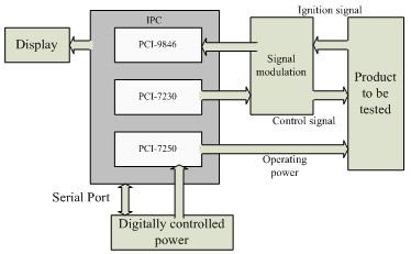
According to the operating requirements of operational characteristics, automation and generalization of electronic time fuse testing, virtual instrumental technology is much in line with the program requirements and can better achieve the results the program expects. ADLINK Technology has a rich virtual instrumental test and measurement product line, and is capable of providing a wider selection. LabVIEW development software is easy to learn and use. It can be utilized to develop complex, parallel, effective and easy-to-operate testing systems quickly and conveniently. In order to reduce the cost of the system, it was decided to select an IPC equipped with PCI cards and expansion USB ports, serial ports and other modular units to perform data exchange and testing, and develop the new testing system under the LabVIEW software platform. The overall program design is shown in Figure 1:

Figure 1 Overall program block diagram

A digital program controlled power supply is used to provide operating power to the electronic time fuse and the setter to be tested. It has four programmable and 4 fixed voltage outputs with input voltages ranged between -12V and +36V. The IPC computer can perform programming through the serial interface to have its output voltage meet the operating power requirements of different models of electronic time fuses and setters.


Setting signals, initiation signals, ignition signals, operating voltage and operating current etc. that are related to fuse input and output signals are monitored in waveform format and collected by the PCI-9846 high-speed digitizer.


The initiation control, mode control and other digital control signals of electronic time fuses and setters as well as the monitoring of intermediate signals during the operation of fuse and setter are completed by the PCI-7230 isolated digital I/O card.


The operating power supplier for the product to be tested has its output control managed by the PCI-7250 relay output card through the relay.


The signal modulation circuit mainly modulates all kinds of the signals from the electronic time fuse and the setter to be tested into the acceptable range of the test boards and cards, e.g. signal pull high, pull low matching; all kinds of switches with normally-open, normally-closed contact matching; analog, digital, pulse level, voltage modulation; signal filtering, amplification and other modulations.


The product to be tested and the general testing system are connected by specialized test cabling. When testing electronic time fuses and setters of different model number, it is only necessary to change the testi cabling and call for corresponding testing software and parametrical settings.

3. Realization of key modular software and hardware


Based on the deficiencies of traditional electronic time fuse testing systems, the new testing program is hoped to achieve the following results:

 
  • Testing the parametrical setting function

    When the electronic time fuse performs parametrical settings, in order to meet the requirement of prompt responses, it has to transmit as much data as possible within a minimal time interval. Therefore, the length of its encoded setting is not likely to be too long. The signal with the shortest code length is on the order of microseconds. Moreover, in some operating environments, parametrical setting work proceeds continuously, accompanying the operation of the weapon system until munitions are launched. Thus, when performing reliability testing on the setting of a product, prolonged continuous setting testing is required. From the characteristics listed above that are related to the performing of parametrical setting functional testing, it can be learned that the key to completing that testing is that the testing system should simultaneously possess the twin characteristics of a higher sampling rate and longer data storage.

    The PCI-9846 high-speed digitizer by ADLINK Technology is 4-channel high-speed data acquisition equipment with a 40MS/s sampling rate per channel and 16-bit sampling resolution, which can satisfy the needs of real-time high-resolution acquisition of setting signal waveforms. It is also equipped with 512MB memory on board that frees it from the PCI bus bandwidth limitation and renders it capable of storing more waveforms in a longer time, which satisfies the operating requirements for a large data storage capacity needed for performing continuous setting reliability testing.

    The input impedance of PCI-9846 digitizer is 50�[ or 1M�[ and its input range is ��1V or ��5V. The above two parameters can be adjusted by software. Therefore, for products set by digital signal, acquisition and handling can be performed directly; while, for products set by analog signal, because its setting signal amplitude can exceed the input range of the digitizer, the analog signals are voltage divided by the signal modulation circuit and transformed to within the range of ��5V for performing acquisition.

    During setting performance testing, the main control program will confirm output operating voltage according to the model number of the product to be tested and provide operating power through the relay controlled output power in the PCI-7250 relay output card, before transmitting setting parameters to the setter via serial port and starting the data acquisition subprogram (refer to Figure 2). The data acquisition subprogram-controlled digitizer starts to collect the feature signals delivered by the signal modulation circuit, where one channel records the waveform of the setting signal, one channel detects the operating power signal provided to the product, and one channel detects the operating current signal of the product. In the meantime, an initiation signal is delivered by the digital output port of PCI-7230 to the setter. After detecting that all the setting signals have been transmitted, the system stops data acquisition and starts to perform analysis and processing for the signal data collected. Through the measurement of the amplitude, code width, and duty cycle of the setting signal, and parameters including operating voltage, operating current and etc., judgment on the performance index of the product is given.

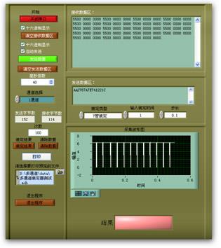
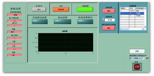
    When performing continuous setting functional testing, the main control program will continuously transmit initiation control signals to the setter and control the operation of the setter through PCI-7230 after initiating the data acquisition subprogram. The whole testing process takes 10,000 loops in total. Simultaneously with transmitting continuous setting signals to the setter the testing system will continuously collect parameters including signal waveforms, operating voltage and operating current etc. from the fuse setter line under testing. The main control program then reads the waveform data collected from the on-board memory in the digitizer and stores in a real-time manner. After the whole testing process finishes, the main control software will stop data acquisition and read back stored data to start analysis and processing. The restored signal waveforms will be displayed and each group of setting signals will then have its performance analyzed, the reliability of parametrical settings determined, and statistical results revealed. The data analysis and processing interface is shown in Figure 3 below.
Figure 2 Data acquisition subprogram
Figure 3 Continuous setting testing data analysis interface
  • Testing the accuracy of electronic time fuse clocking

    The clocking time of electronic time fuses is the time difference from the time it starts clocking after receipt of the clock starting signal to the time the ignition signal is delivered. According to the differences of the application background of different models, the clocking accuracy and clocking time range varies hugely. For the electronic time fuses in Close-in Weapon System (CIWS) munitions, its clocking accuracy needs to within microsecond level and the length of clocking time should be longer than 100 milliseconds. The most important factor for performing clocking accuracy testing is that the sampling rate should be high enough. On the other hand, the electronic time fuses used in long-distance suppression weapon systems have a clocking accuracy measured at the millisecond level, but the length of clocking time is usually longer than 400 seconds. The sampling rate during testing can be appropriately reduced in order to meet the requirement of prolonged data acquisition.

    According to the above characteristics, when performing clocking accuracy testing on different models of electronic time fuses, the sampling rate of the digitizer can be controlled by software from 1MS/s to 40MS/s, which ensures the precondition of time testing accuracy and saves system resources.

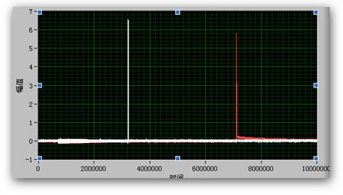
    When conducting clocking accuracy testing, the main control program will determine the operating voltage to be supplied to the product to be tested according to its model number, and then deliver output control to the product to be tested through the relay output card. The operating data acquisition subprogram is then started and the initiation control signal is transmitted simultaneously to the fuse to be tested to start its clocking. The testing system will synchronously monitor the initiation control signal, ignition output signal, operating voltage and operating current etc. of the fuse to be tested. When the ignition signal is detected, data acquisition will be stopped and the analysis and processing for the data collected will be started. The time from the time the initiation signal is started to the output time of the ignition signal is the fuse clocking time. In the meantime, the ignition signal waveform of the fuse is also being analyzed; the maximum voltage with respect to the ignition signal is measured, the integral of the ignition signal waveform is calculated, and the parameters of the ignition signal including amplitude, energy, operating voltage, and operating current will be assessed to determine whether they meet the criteria of performance indexes. Figure 4 shows the waveforms of the initiation signal and the ignition signal collected by the testing system from one electronic time fuse.
Figure 4 Waveforms of the initiation signal and the ignition signal from one electronic time fuse
  • Generation of product control signal

    The control signals of electronic time fuses and setters during their operation are mostly digital I/O signals. Therefore, the PCI-7203 isolated digital input output card was chosen to generate the product control signal. This card has 16 channels of isolated digital input and 16 channels of isolated digital output function. Its output channel has a wide output range between 5-35V, which can satisfy the operating requirements of all kinds of control signals of different models of electronic time fuses and setters. The digital input channel has an input range between 0-24V and is capable of monitoring changes of all kinds of intermediate signals of fuses and setters during their operation.

    During system testing, the required digital power supply voltage is confirmed according to the model of product to be tested, and then the data transmission to setter is completed through serial ports. The setting initiation signal is then transmitted via digital output channel 1 to control the setter and start its operation. After setting is finished, the fuse clocking initiation signal will be transmitted via digital output channel 2 and the fuse to be tested will start clocking. Based on the requirements of different fuses, all the intermediate characteristic signals of the fuse to be tested are monitored through the digital input channel in a real-time manner. If the test has an electronic time fuse with time modification function, after the fuse starts clocking, the modification signal pulse should be transmitted to the fuse to be tested through another 3 output channels. Figure 5 is the waveform of the output initiation control signal.
Figure 5 The initiation control signal output by the testing system

4. Software design of the testing system


The control software of the electronic time fuse general testing system works under Windows OS platform and is developed on the LabVIEW 8.5 platform. The concept of modularized programming is adopted and top-to-bottom design is applied. In order to fulfill the requirements of high-speed acquisition, multi-threaded programming is utilized: one thread is for user interface, one for data acquisition and one for instrumental control. It has an excellent human-machine interface for the functions including data acquisition, data analysis, storage and automatic report generation etc. The main process of the system testing software is shown in Figure 6.

Figure 6 Software design process for the general testing system
  1. Select product model

    Based on the model of product to be tested, select the corresponding product model number on the operation interface. System control software will automatically upload corresponding systematic setting parameters according to the model number of the product to be tested.

  2. Power setup

    System control software will encode required power parameters and transmit them to the digital program-controlled power through serial ports according to the loaded operating power parameters of the product to be tested. The digital program-controlled power performs automatic modifications on system operating power based on the power parameters received and return the modification results to the system control software.

  3. Select test item

    According to the testing requirements of different fuses, different test content including setting performance test, continuous setting reliability test, clocking accuracy functional test etc. can be selected. And the test conditions associated with different test items can also be selected, e.g. high temperature, low temperature, vibration etc. The corresponding testing data can be automatically loaded according to the differences of test content and test project.

  4. Functional test

    Following the selection of the previous three items, the functional test will be automatically started after clicking. The system controls the operation of the product to be tested by control signals and collects related characteristic signals during the operation of the product to be tested. Each test item is packed in a sub-VI, which is convenient for the use of main-VI and TestStand. Test data can be automatically loaded or can be modified prior to test start, altering settings such as setting time, modification time etc.

  5. Data processing and storage

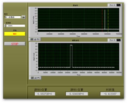
    After completion of a test, all testing information and data is recorded, analyzed, processed and stored, including current test date, time, test data and the status of each test project (not tested, pass, fault information) etc. The data processing and storage interface is shown in Figure 7.

  6. Automatic generation of reports

    When a print out or test report is required, the report generation tool kit of LabVIEW can be utilized and called for a corresponding report template, or by TestStand, to automatically generate necessary reports and files with the content of the stored data in template format.
Figure 7 Data processing and storage interface

5. Test and performance validation


Graphical, real-time and dynamic display of measurement data is an essential function for test instruments such as the commonly found digital oscilloscope, spectrum analyzer etc. These devices are equipped with CRT monitors to show the measurement signal waveform and the operating state of the instrument. LabVIEW controls waveform display through real-time trend diagram controls, which will continuously add new data to the end of the existing data, so the waveform is shown in a forward-moving manner. The signal changing process during the operating process of the fuse can therefore be clearly observed and the changing of the signals to be tested can be monitored in real-time.


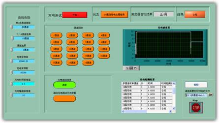
For real-time display of testing system data, select from the relevant item from the ��Channel Replay�� column for the multi-threaded signals of the fuse. The waveform of a channel can be displayed. When the data is replayed, the displayed waveform can be zoomed in or zoomed out to change its size. Figure 8 shows the waveform in one channel of this testing system.

Figure 8 Waveform diagram of one channel of this testing system

The objective of fuse testing is to acquire the operating performance, status or characteristic signals of the fuse, so data acquisition is only the first step of the testing task. Data analysis and processing are a key portion of a testing system. Traditional fuse test data is processed by tools like DSP or MATLAB, but this testing system utilizes the varied features of LabVIEW software and its powerful analysis tool kits that can easily handle complex data analysis and processing work. Its data processing utilizes tool kits and is processed in the background. The test results will indicate the verdict of pass or fail immediately after the completion of processing, which can help testers to understand the test results with a quick glance.


After the design of a testing system is finished, several conditions can be set up to test the actual performance of the system. Through the operation performed by the testers, the average testing time for a single product is measured; through multiple tests, the system reliability can be validated; through setup of faults, the level of system detection rate can be tested; through signal comparison and locating, testing accuracy of the system can be tested. All the tests conducted indicate that the single product testing time of the testing system has been shortened by more than 50%, while testing accuracy, reliability and detection rate are also improved. From the perspectives the requirements of automation and generalization, both are met by the system design.

Conclusions


By focusing on the operational requirements of operating characteristics, automation, and generalization for electronic time fuses, this testing system utilizes virtual instrumental technology with an IPC equipped with hardware including a high-speed digitizer, digital I/O, replay output cards etc. by ADLINK Technology. The graphical software programming of LabVIEW is integrated to develop a powerful, effective, easy-to-use, and easily expandable electronic time fuse general testing system. Automated control over the testing process and steps, measurement data analysis and processing and automatic judgment on fault modes are realized, which obviously improved testing efficiency, testing accuracy and detection rate. Compared with traditional testing approaches, virtual instrumental testing has greater advantages, which ensure wider, more in-depth applications can be implemented quickly.


Related ADLINK Links:

  • More about ADLINK Digitizers
  • More about PCI-9816/9826/9846
Distributed Temperature Sensing with High-Resolution Digitizers 回列表 Design of a Testing Apparatus for AIR Navigation Vor Signals
  • 關於我們
  • 使命與願景
  • 企業永續
  • 投資人關係
  • 新聞與活動
  • 加入凌華
  • 聯絡我們
  • 全球據點
  • 全球經銷商
  • 服務
  • 諮詢技術專家
  • 合作夥伴
  • eRMA服務
  • 關注我們
隱私權政策
Cookie 政策
網站地圖
關於凌華全球據點支援
  •    
  •    
  •    
  •    
Copyright © 2025 ADLINK Technology Inc. All Rights Reserved.
TEL:(03) 216-5088 TEL:(03) 216-5088 FAX:(03) 328-5706 Email:tw@adlinktech.com Address:桃園市龜山區華亞一路66號