• 購物車(0)
繁體中文
English
简体中文
한국어
日本語
繁體中文
  • 登錄
  • 產品
    嵌入式模組化電腦
    • COM-HPC
    • COM Express
    • OSM
    • SMARC
    • Qseven
    • ETX
    GPU解決方案
    • MXM GPU 模組
    • PCIe 顯示卡
    強固型運算
    • CompactPCI & CompactPCI Serial
    • VPX
    • PC104
    • AVA Railway Rugged Computers
    • PIDS
    邊緣運算平台
    • 工業電腦 / 主機板 / 單板電腦
    • 嵌入式電腦 / IoT Gateway
    • 邊緣 AI 運算平台
    • AI 智慧相機
    • 機器人控制器
    • 工業級固態硬碟 (SSD)
    工業級顯示系統與平板電腦
    • 工業級觸控顯示器
    • Open Frame 平板電腦
    • All-in-One 平板電腦
    • 強固型面板電腦
    • 數位看板播放器
    車用解決方案
    • 自動駕駛解決方案
    • AI-ADAS 解決方案
    網路通訊與伺服器
    • AI GPU 伺服器
    • 工業級邊緣伺服器
    • 網路安全平台
    • P5G 工業自動化專網-MicroRAN
    自動化與控制
    • 機器視覺
    • 運動控制與 I/O
    • EtherCAT 運動控制解決方案
    • HMI 平板電腦
    • 資料擷取模組
    • GPIB 與數字化儀
    • PXI 平台與模組
    • 自主移動機器人
    • 工業物聯網閘道器
    設計與製造服務
    • DMS+ (ODM/OEM 服務)
    醫療專用電腦與顯示器
    • 醫療專用觸控電腦
    • 醫療專用顯示器
    • 醫療專用 BOX PC
    軟體
    • EdgeGO
  • 產業
    車用解決方案 軍工與航太 娛樂資訊 智慧醫療 半導體解決方案 智慧製造 鐵路 機器人技術

    車用解決方案

    車用解決方案

    凌華科技的自動駕駛運算平台採用尖端技術,致力提供更安全、更高效的駕駛運行。以強大的運算能力,滿足自動駕駛和先進駕駛輔助系統(ADAS)技術,並提供適用於汽車的堅固設計。

    了解更多

    軍工與航太

    軍工與航太

    在軍工航太領域中,準確觀察環境並做出快速可靠的決策並及時採取行動至關重要。 凌華科技強固的系統和Data Distribution Service(DDS)是大型數據基礎架構的關鍵,該基礎架構可收集、儲存、分析資訊並將資訊從現場傳遞給決策者。

    了解更多

    娛樂資訊

    娛樂

    凌華科技博弈平台解決方案透過我們的軟、硬體和顯示產品為全球遊戲機製造商提供全面性的服務。 我們將電腦專業知識與尖端軟體完美結合,並遵循博弈產業的要求和法規限制來為我們客戶提供服務,使他們能夠專注於打造世界上最好的娛樂體驗。

    了解更多

    智慧醫療

    智慧醫療

    凌華科技專注於醫療可視化設備和經過醫療認證的解決方案,來滿足智慧醫療數位化的需求。 透過PENTA在醫療領域的設計和製造能力,凌華科技的智慧醫療解決方案可加速各種醫療環境中的智慧轉型。

    了解更多

    半導體解決方案

    半導體解決方案

    你所能想像的一切,都因晶片而有所改變。為了滿足不同應用的需求,完美的晶圓製造對於品質的工藝要求到效率和生產力的過程都無比講究。

    了解更多

    智慧製造

    智慧製造

    借由邊緣運算,ADLINK 智慧製造解決方案加速更快的數據決策,為半導體和電子製造業創造更具彈性和安全性的生產環境。

    了解更多

    鐵路

    鐵路

    我們的強固設計 CompactPCI、模組化電腦、工業級系統及平板電腦系列產品特別獲選納入車載 ATO/DMI 及軌旁 CTC/RBC/TSR 鐵路解決方案。凌華科技在設計和製造方面的卓越靈活性廣受全球鐵路號誌領導供應商的青睞。

    了解更多

    機器人技術

    機器人技術

    自主移動機器人(AMR)能夠在沒有或最低限度的人工操作監督之下來執行工作。在一些可以使用大量的AMR設施譬如學校、醫院、大型購物中心和工廠之類的,以提高營運效率和生活品質。

    了解更多
  • 策略夥伴
    AMD Ampere Arm Intel MediaTek NVIDIA NXP Qualcomm

    AMD-based Solutions

    AMD-based Solutions by ADLINK

    Empower your edge computing with ADLINK, a leading company enabling edge solutions. Leverage AMD's high performance, secure integration, and power efficiency advantages for a wide range of edge, networking, and edge systems with x86 core architecture. Experience superior processing and graphics performance with ADLINK's utilization of AMD Ryzen™ Embedded series, powered by Radeon™ RX, perfect for industrial, medical, automation and gaming applications.

    Learn More

    Ampere-based Solutions

    Ampere-based Solutions by ADLINK

    Experience the future of edge computing with our comprehensive offering, which includes the Ampere Altra-based COM-HPC module, a developer platform and/or dev kit. Dive in now to unleash superior performance, energy efficiency, and optimized TCO in applications including but not limited to industrial automation, autonomous vehicles, transportation, healthcare, video surveillance, and energy management.

    Learn More

    Arm-based Solutions

    Arm-based Solutions by ADLINK

    Based on Arm architecture, ADLINK also collaborates with Ampere, NXP, MediaTek, Qualcomm, and Rockchip in module computing development and value-added solutions across varied industries, including smart manufacturing, autonomous driving, robotics, AMR, drone, transportation, logistics, retail, infotainment, healthcare, security, and more.

    With plug-and-play tools, development kits, and all-encompassing systems, ADLINK and Arm empowers developers to accelerate and realize their innovations.

    Learn More

    Intel-based Solutions

    Intel based Solutions by ADLINK

    ADLINK is a Titanium member in Intel® Partner Alliance. From modular computing to system-ready use cases, ADLINK works closely with Intel to provide scalable, interoperable solutions that accelerate your intelligent device deployment with end-to-end analytics.

    Utilizing Intel-based modules, ADLINK accelerates your products’ time to market with edge AI platform development support while addressing diverse industry pain points, such as in networking, smart manufacturing, autonomous driving, AMR, transportation, healthcare, retail, and infotainment.

    Learn More

    MediaTek-based Solutions

    MediaTek-based Solutions by ADLINK

    ADLINK Technology and MediaTek are strategic partners that deliver innovative and powerful solutions for edge computing and edge AI applications. Leveraging MediaTek's flagship, power-efficient Genio platform SoCs and ADLINK's expertise in embedded and rugged designs, they provide high-performance, energy-efficient, and reliable modules and platforms in accomplishing various IoT use cases, such as smart home, human-machine interface, multimedia, industrial IoT, and robotics.

    Learn More

    NVIDIA-based Solutions

    NVIDIA-based Solutions by ADLINK

    To fulfill industry-specific requirements, ADLINK is able to efficiently develop edge AI platforms, AI smart cameras, medical platforms, and AI portable GPU accelerators based on NVIDIA Jetson modules, the NVIDIA IGX platform, and RTX Embedded GPUs for applicable industries, including smart manufacturing, autonomous driving, autonomous mobile robots (AMR), robotics, transportation, healthcare, logistics, retail, infotainment, AI development, professional graphics, and gaming.

    Learn More

    NXP-based Solutions

    NXP-based Solutions by ADLINK

    Utilizing NXP's i.MX 8 and i.MX 9 series technology, ADLINK offers edge-connected solutions to assist medical, test & measurement, automation, and smart city customers reduce TCO. This combination of NXP's technology with ADLINK's R&D experience in edge computing provides versatile and dynamic solutions for critical applications.

    Learn More

    Qualcomm-based Solutions

    Qualcomm-based Solutions by ADLINK

    Qualcomm Technologies’ portfolio of leading robotics and drones solutions is driving next-generation use cases, including autonomous deliveries, mission critical use cases, commercial and enterprise drone applications and more.

    Among them, the Qualcomm QRB5165 solution is designed to help build consumer, enterprise or industrial robots with 5G connectivity, on-device AI and machine learning, superior computing, and intelligent sensing capabilities. By adopting Qualcomm QRB5165, ADLINK’s module will enable the proliferation of 5G in robotics and intelligent systems.

    Learn More
    EdgeOpen Voices

    EdgeOpen™ Voices

    了解業界專家如何透過實際案例與實務洞察推動邊緣 AI 發展。

    立即查看
  • 支援

    支援

    夥伴中心eRMA 服務凌華科技 DDS 支援

    下載

    軟體與驅動程式下載凌華科技 DDS宣傳手冊Content Hub凌華科技 GitHub

    聯絡我們

    銷售諮詢諮詢技術專家全球經銷商

    若您有任何價格、產品庫存問題,或需要任何技術上的協助,歡迎隨時與我們連繫。

    了解更多
  • 關於我們

    價值

    品質政策與資源合作夥伴企業永續環境責任政策CapabilitesProduct Security

    公司

    關於凌華全球據點投資人關係公司簡介企業logo與品牌規範人才招募

    新聞

    新聞與活動Podcast部落格
    Support

    公司新聞、產品資訊、近期活動或技術部落格,一手掌握ADLINK的最新資訊。

    了解更多
  • 首頁
  • Design of a Testing Apparatus for AIR Navigation Vor Signals
  • 首頁
  • Design of a Testing Apparatus for AIR Navigation Vor Signals
繁體中文
English
简体中文
한국어
日本語
繁體中文
  • 登錄
  • 登錄
  • home
    • 產品
      嵌入式模組化電腦+ GPU解決方案+ 強固型運算+ 邊緣運算平台+ 工業級顯示系統與平板電腦+ 車用解決方案+ 網路通訊與伺服器+ 自動化與控制+ 設計與製造服務+ 醫療專用電腦與顯示器+ 軟體+
      COM-HPCCOM ExpressOSMSMARCQsevenETX
      MXM GPU 模組PCIe 顯示卡
      CompactPCI & CompactPCI SerialVPXPC104AVA Railway Rugged ComputersPIDS
      工業電腦 / 主機板 / 單板電腦嵌入式電腦 / IoT Gateway邊緣 AI 運算平台AI 智慧相機機器人控制器工業級固態硬碟 (SSD)
      工業級觸控顯示器Open Frame 平板電腦All-in-One 平板電腦強固型面板電腦數位看板播放器
      自動駕駛解決方案AI-ADAS 解決方案
      AI GPU 伺服器工業級邊緣伺服器網路安全平台P5G 工業自動化專網-MicroRAN
      機器視覺運動控制與 I/OEtherCAT 運動控制解決方案HMI 平板電腦資料擷取模組GPIB 與數字化儀PXI 平台與模組自主移動機器人工業物聯網閘道器
      DMS+ (ODM/OEM 服務)
      醫療專用觸控電腦醫療專用顯示器醫療專用 BOX PC
      EdgeGO
      AdvancedTCA 交換器AdvancedTCA 平台AdvancedTCA 刀鋒伺服器
      嵌入式固態硬碟
      COM-HPC Server Type COM-HPC Client Type
      COM Express Type 6 COM Express Type 7 COM Express Type 10 COM Express Type 2
      MXM 3.1 Type A MXM 3.1 Type B
      Pocket AI (可攜式GPU)
      3U VPX 刀鋒伺服器 6U VPX 刀鋒伺服器 VPX 顯示卡, XMC模組
      Mini-ITX 嵌入式主機板 可擴充式無風扇電腦 嵌入式無風扇電腦 ATX 主機板 嵌入式板卡 工業電腦系統 PICMG 單板電腦 無電源背板 工業電腦周邊 工業電腦機箱
      搭載NVIDIA Jetson系列
      ROS2 解决方案 凌華科技ROS2 Github NeuronSDK
      2U 網路安全平台 4U 網路安全平台
      圖像擷取卡/視頻擷取卡 影像分析工具 智慧相機 視覺系統 人工智慧機器視覺設備
      集中式運動控制器 分散式運動控制器 編碼器和觸發器 運動控制軟體和工具
      設備狀態監測與維護平台 資料擷取模組 數字化儀 / 示波器
      PXI 機箱 PXI 控制器 PXI/PXIe 模組 遠端控制器
      AMR
    • 產業
      車用解決方案 軍工與航太 娛樂資訊 智慧醫療 半導體解決方案 智慧製造 鐵路 機器人技術

      車用解決方案

      車用解決方案

      凌華科技的自動駕駛運算平台採用尖端技術,致力提供更安全、更高效的駕駛運行。以強大的運算能力,滿足自動駕駛和先進駕駛輔助系統(ADAS)技術,並提供適用於汽車的堅固設計。

      了解更多

      軍工與航太

      軍工與航太

      在軍工航太領域中,準確觀察環境並做出快速可靠的決策並及時採取行動至關重要。 凌華科技強固的系統和Data Distribution Service(DDS)是大型數據基礎架構的關鍵,該基礎架構可收集、儲存、分析資訊並將資訊從現場傳遞給決策者。

      了解更多

      娛樂資訊

      娛樂

      凌華科技博弈平台解決方案透過我們的軟、硬體和顯示產品為全球遊戲機製造商提供全面性的服務。 我們將電腦專業知識與尖端軟體完美結合,並遵循博弈產業的要求和法規限制來為我們客戶提供服務,使他們能夠專注於打造世界上最好的娛樂體驗。

      了解更多

      智慧醫療

      智慧醫療

      凌華科技專注於醫療可視化設備和經過醫療認證的解決方案,來滿足智慧醫療數位化的需求。 透過PENTA在醫療領域的設計和製造能力,凌華科技的智慧醫療解決方案可加速各種醫療環境中的智慧轉型。

      了解更多

      半導體解決方案

      半導體解決方案

      你所能想像的一切,都因晶片而有所改變。為了滿足不同應用的需求,完美的晶圓製造對於品質的工藝要求到效率和生產力的過程都無比講究。

      了解更多

      智慧製造

      智慧製造

      借由邊緣運算,ADLINK 智慧製造解決方案加速更快的數據決策,為半導體和電子製造業創造更具彈性和安全性的生產環境。

      了解更多

      鐵路

      鐵路

      我們的強固設計 CompactPCI、模組化電腦、工業級系統及平板電腦系列產品特別獲選納入車載 ATO/DMI 及軌旁 CTC/RBC/TSR 鐵路解決方案。凌華科技在設計和製造方面的卓越靈活性廣受全球鐵路號誌領導供應商的青睞。

      了解更多

      機器人技術

      機器人技術

      自主移動機器人(AMR)能夠在沒有或最低限度的人工操作監督之下來執行工作。在一些可以使用大量的AMR設施譬如學校、醫院、大型購物中心和工廠之類的,以提高營運效率和生活品質。

      了解更多
    • 策略夥伴
      AMD Ampere Arm Intel MediaTek NVIDIA NXP Qualcomm

      AMD-based Solutions

      AMD-based Solutions by ADLINK

      Empower your edge computing with ADLINK, a leading company enabling edge solutions. Leverage AMD's high performance, secure integration, and power efficiency advantages for a wide range of edge, networking, and edge systems with x86 core architecture. Experience superior processing and graphics performance with ADLINK's utilization of AMD Ryzen™ Embedded series, powered by Radeon™ RX, perfect for industrial, medical, automation and gaming applications.

      Learn More

      Ampere-based Solutions

      Ampere-based Solutions by ADLINK

      Experience the future of edge computing with our comprehensive offering, which includes the Ampere Altra-based COM-HPC module, a developer platform and/or dev kit. Dive in now to unleash superior performance, energy efficiency, and optimized TCO in applications including but not limited to industrial automation, autonomous vehicles, transportation, healthcare, video surveillance, and energy management.

      Learn More

      Arm-based Solutions

      Arm-based Solutions by ADLINK

      Based on Arm architecture, ADLINK also collaborates with Ampere, NXP, MediaTek, Qualcomm, and Rockchip in module computing development and value-added solutions across varied industries, including smart manufacturing, autonomous driving, robotics, AMR, drone, transportation, logistics, retail, infotainment, healthcare, security, and more.

      With plug-and-play tools, development kits, and all-encompassing systems, ADLINK and Arm empowers developers to accelerate and realize their innovations.

      Learn More

      Intel-based Solutions

      Intel based Solutions by ADLINK

      ADLINK is a Titanium member in Intel® Partner Alliance. From modular computing to system-ready use cases, ADLINK works closely with Intel to provide scalable, interoperable solutions that accelerate your intelligent device deployment with end-to-end analytics.

      Utilizing Intel-based modules, ADLINK accelerates your products’ time to market with edge AI platform development support while addressing diverse industry pain points, such as in networking, smart manufacturing, autonomous driving, AMR, transportation, healthcare, retail, and infotainment.

      Learn More

      MediaTek-based Solutions

      MediaTek-based Solutions by ADLINK

      ADLINK Technology and MediaTek are strategic partners that deliver innovative and powerful solutions for edge computing and edge AI applications. Leveraging MediaTek's flagship, power-efficient Genio platform SoCs and ADLINK's expertise in embedded and rugged designs, they provide high-performance, energy-efficient, and reliable modules and platforms in accomplishing various IoT use cases, such as smart home, human-machine interface, multimedia, industrial IoT, and robotics.

      Learn More

      NVIDIA-based Solutions

      NVIDIA-based Solutions by ADLINK

      To fulfill industry-specific requirements, ADLINK is able to efficiently develop edge AI platforms, AI smart cameras, medical platforms, and AI portable GPU accelerators based on NVIDIA Jetson modules, the NVIDIA IGX platform, and RTX Embedded GPUs for applicable industries, including smart manufacturing, autonomous driving, autonomous mobile robots (AMR), robotics, transportation, healthcare, logistics, retail, infotainment, AI development, professional graphics, and gaming.

      Learn More

      NXP-based Solutions

      NXP-based Solutions by ADLINK

      Utilizing NXP's i.MX 8 and i.MX 9 series technology, ADLINK offers edge-connected solutions to assist medical, test & measurement, automation, and smart city customers reduce TCO. This combination of NXP's technology with ADLINK's R&D experience in edge computing provides versatile and dynamic solutions for critical applications.

      Learn More

      Qualcomm-based Solutions

      Qualcomm-based Solutions by ADLINK

      Qualcomm Technologies’ portfolio of leading robotics and drones solutions is driving next-generation use cases, including autonomous deliveries, mission critical use cases, commercial and enterprise drone applications and more.

      Among them, the Qualcomm QRB5165 solution is designed to help build consumer, enterprise or industrial robots with 5G connectivity, on-device AI and machine learning, superior computing, and intelligent sensing capabilities. By adopting Qualcomm QRB5165, ADLINK’s module will enable the proliferation of 5G in robotics and intelligent systems.

      Learn More
      EdgeOpen Voices

      EdgeOpen™ Voices

      了解業界專家如何透過實際案例與實務洞察推動邊緣 AI 發展。

      立即查看
    • 支援

      支援

      夥伴中心eRMA 服務凌華科技 DDS 支援

      下載

      軟體與驅動程式下載凌華科技 DDS宣傳手冊Content Hub凌華科技 GitHub

      聯絡我們

      銷售諮詢諮詢技術專家全球經銷商

      若您有任何價格、產品庫存問題,或需要任何技術上的協助,歡迎隨時與我們連繫。

      了解更多
    • 關於我們

      價值

      品質政策與資源合作夥伴企業永續環境責任政策CapabilitesProduct Security

      公司

      關於凌華全球據點投資人關係公司簡介企業logo與品牌規範人才招募

      新聞

      新聞與活動Podcast部落格
      Support

      公司新聞、產品資訊、近期活動或技術部落格,一手掌握ADLINK的最新資訊。

      了解更多
繁體中文
English
简体中文
한국어
日本語
繁體中文
  • 登錄

Design of a Testing Apparatus for AIR Navigation Vor Signals

Wu Guangbo, Liu Liansheng
Fundamental Experiment Center,
Civil Aviation University of China


Application


Testing of air navigation equipment, signal generation, and signal collection.


Challenge


In the testing of avionic equipment, it is required that multifunctional automatic testing systems be constructed with limited resources. As is well known, airborne electronic equipment uses numerous complex signals, including low-frequency and high-frequency signals, continuous and discrete signals, and even non-electric signals. Conventional testing systems, typically composed of separate instruments, are costly but have a low degree of test automation and low expandability. With the development of the civil air transportation industry, most airborne electronic equipment has been highly digitized and integrated, making it impossible to test or check the equipment manually. Hence conventional testing instruments have failed to meet practical needs. By contrast, signal processing mechanisms based on software-defined radio are advantageously flexible and open and therefore meet said needs. Such advantageous features also facilitate teaching, learning, and research.


Solution


This study is directed to air navigation VOR signals by way of example. Research was made on the principle of VOR navigation, followed by analyses and modeling of VOR composite signals. The time-domain data of waveforms can be conveniently expressed and calculated with equations. In this study, the time-domain data obtained were input into a DAC to generate simulated waveforms, which were then up-converted to the desired frequency. Existing analog signals were collected with a PCI-9846 high-speed digitizer, and the data collected was displayed in real time or stored as files for subsequent use and analysis. It has been verified that the application of software-defined radio to an automatic testing system can save costs significantly, simplify the system, and increase efficiency. In addition, the performance indices of the digitizer satisfy practical needs.


Air navigation VOR (Very High Frequency Omnidirectional Range) signals are collected with the PCI-9846 high-speed digitizer from ADLINK Technology, subjected to time-domain and frequency-domain analyses, and then demodulated to restore directional information. Thus, accuracy of the signals can be rapidly checked. It has been verified that the application of software-defined radio to an automatic testing system can save costs significantly, simplify the system, and increase efficiency. Moreover, the performance indices of the digitizer satisfy practical needs.


In the testing of avionic equipment, it is required that multifunctional automatic testing systems be constructed with limited resources. As is well known, airborne electronic equipment uses numerous complex signals, including low-frequency and high-frequency signals, continuous and discrete signals, and even non-electric signals. Conventional testing systems, typically composed of separate instruments, are costly but have a low degree of test automation and low expandability. With the development of the civil air transportation industry, most airborne electronic equipment has been highly digitized and integrated, making it impossible to test or check the equipment manually. Therefore, developed countries are now using automatic testing equipment to perform related tasks. [1][2]


The fundamentals of software-defined radio consist of a general-purpose, standard, modular hardware platform which carries out the various functions of a radio station by means of software programming, as opposed to conventional hardware-based, application-oriented radio station design methods [3]. An automatic testing system has higher requirements for the flexibility and comprehensiveness of the signal source, so the traditional signal generators no longer meet these needs [4]. By contrast, signal generators based on software-defined radio are advantageously flexible and open and are therefore suitable for use. These advantageous features also facilitate teaching, learning, and research.


In this study, the PCI-9846H of ADLINK is applied to the testing and calibration of the signal source of an automatic testing system, and air navigation VOR signals are collected and processed to restore basic information. It has been proved that the performance indices of the digitizer satisfy practical needs.

1.VOR Signal


Basically, a very high frequency omnidirectional range signal provides a complex radio signal to an airborne VOR signal receiver, which demodulates the signal to determine the magnetic bearing, i.e., VOR bearing, of the VOR signal station on land in relation to the aircraft [5]. The spatial VOR composite signal received by the airborne receiver includes a reference-phase signal and a variable-phase signal. Orientation can be accomplished by comparing the phases of these two signals. The operating frequency of a VOR signal ranges from 108MHz to 117.95MHz, with a channel spacing of 0.05MHz.


1.1 VOR Reference-Phase Signal


A VOR reference-phase signal includes a radio-frequency (RF) carrier and a 9960Hz subcarrier. The frequency of the RF carrier ranges from 108MHz to 117.95MHz. The 9960Hz subcarrier is frequency-modulated by a 30Hz reference signal, with a modulation index of 16, as expressed by the following equation:

where is the modulation index of the subcarrier on the RF carrier, is the frequency of the subcarrier, is the modulation index on the subcarrier, is the frequency of the baseband signal, and is the RF frequency.


A reference-phase signal has a constant signal radiation intensity in every radial direction, i.e., from 0° to 360°, and the phase of the 30Hz signal is also radially constant from 0° through 360°. Therefore, in terms of radiation patterns, the horizontal directivity pattern is a circle.


1.2 VOR Variable-Phase Signal


A variable-phase signal only includes a simple RF carrier, whose frequency ranges from 108MHz to 117.95MHz. Two pairs of orthogonal sideband antennae radiate a sine modulated sideband wave and a cosine modulated sideband wave respectively, and the field intensities of these waves vary regularly at 30Hz. Thus, a 30Hz amplitude modulated wave featuring regular sinusoidal variation is generated in the space, as can be expressed by:

where is the current VOR radial azimuth.
 

1.3 Composite Signal


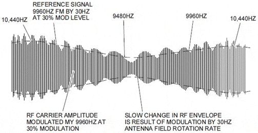
A spatial composite signal is a superposition of a reference-phase signal and a variable-phase signal, as shown in Figure 1 and expressed by the following equation:

A receiver demodulates the composite signal and calculates the phase difference of the two component signals to obtain directional information.[5,6]

Figure 1. Spatial Composite Signal.

2. System Implementation


A GPP (General-Purpose Processor)-based system structure is used, and digital signals are directly processed by an industrial personal computer (PC). A radio system of this kind does not have the physical look of a radio station and provides radio communication solutions entirely from the perspective of software. A GPP is not a real-time synchronization system and therefore is not suitable for real-time processing of signals obtained by strictly timed sampling. A GPP can achieve synchronization to a certain degree only via interruption. Nevertheless, due to its openness, flexibility, programmability and advantages in human-machine interface, a GPP-based system approximates the ideal software-defined radio system and is perfect for testing, teaching, learning, and research purposes.


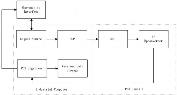
The aforesaid system uses pipeline-like connections, wherein the directions of the pipelines are consistent with signal flows. The pipeline-like connections, featuring high efficiency, a short time delay and a high processing rate, can compensate, to some extent, for the low signal processing speed of the GPP. However, with the modules in the system being physically connected and closely coupled together by circuits and having a low degree of independence from one another, a change in system functions will require the addition of a new module or removal of an existing module, and the corresponding modules, if not the entire structure, must also be changed. In this study, the pipeline-like structure as shown in Figure 2 is chosen because the design objective is to test and calibrate the signal source of a testing system in which signals are relatively stable and need not be changed frequently [7]. Signal generation and processing are performed by the aforementioned industrial PC. An arbitrary waveform generator (AWG) realizes waveform output (a digital up-converter card is required in case of high frequencies). For radio transmission and receiving, an additional antenna and RF amplifier will be needed. Signal collection and A/D conversion are accomplished by ADLINK's PCI-9846 high-speed digitizer. The conversion results can be displayed in real time or saved as waveform files for subsequent processing.

Figure 2. System Block Diagram.

2.1 Signal Source


Medium-frequency signals are generated by the arbitrary waveform generator. The arbitrary waveform generator used is one capable of onboard signal processing (OSP), with 16-bit resolution and -91 dBc close-in spurious-free dynamic range (SFDR), and can provide an instrument quality standard for the required digital up-conversion and baseband interpolation applications. Having all the desired functions, the AWG can also generate general-purpose electronic testing signals, with a maximum output range of 12Vpp, a resistive load of 50Ω, and a highest frequency of 43MHz. The up-converter card is built-in with a 2.7 GHz up-converter, featuring high real-time bandwidth, a stable time base, and a precision as high as ±50ppb. In RF generation applications, the up-converter card is tightly integrated with a modular function generator to generate a signal whose frequency ranges from 50kHz to 2.7GHz, with an adjustable gain range of 130dB. The arbitrary waveform generator generates high-frequency VOR signals, which are sent to the up-converter for up-conversion to the desired very high frequency band.


A PXI card is installed in the PXI chassis. With a PXI-PCI extension kit, PXI modules can be controlled via a computer using a fully transparent MXI-4 link connected by a copper cable. Through a bridge built on a PCI-PCI high-bandwidth connection, the MXI-4 enables remote control over the PXI system through the PCI interface of the computer.


2.2 Data Acquisition


Data acquisition is carried out by the ADLINK PCI-9846 high-speed digitizer. The ADLINK PCI-9846 is a 16-bit 4-channel digitizer with a sampling frequency of 40MHz, designed specifically for high-frequency, large dynamic range signals, and allowing a maximum input frequency of 20MHz. The analog input measuring span can be set at ±1V or ±0.2V via software, and a 50 ohm input impedance can be used in order to deal with high-speed high-frequency signals. A highly linear 4-channel 16-bit A/D converter is provided for ideal adaptation to large dynamic range signals such as radar, ultrasonic waves, and software-defined radio.


Equipped with onboard memory as large as 512MB, the PCI-9846 can record waveforms for a long period of time without being limited by the transfer rate of the PCI bus. Digitized signal data are stored in the onboard memory before transmission to the main memory. Data transmission is carried out through SG-DMA (Scatter-Gather Direct Memory Access) so that not only can a higher data transfer rate be provided, but also the system memory can be used more effectively. If the data transfer rate of the digitizer is lower than the available PCI bus bandwidth, the onboard sampling point first-in first-out memory of the PCI-9846 allows data to bypass the onboard memory and be directly transferred to the host memory in real time.


The PCI-9846 can be triggered in a flexible manner, such as by software triggering, external digital triggering, analog triggering through an arbitrary analog channel, and PXI bus triggering. The various triggering options make the PCI-9846 highly adaptive to practical needs. In the post-triggering, delayed triggering, pre-triggering and middle-triggering modes, data around the triggering event are collected. PCI-9846 also allows repeated triggering so that data sections with very short time intervals can be collected. Thanks to the multiple triggering options provided by the PXI backplane, PCI-9846 can readily implement synchronization between a plurality of modules. And thanks to the PXI trigger bus, PCI-9846 can output triggering or time-base signals to the PXI trigger bus when set as "master" and receive triggering or time-base signals from the PXI trigger bus when set as "slave". The PXI backplane also provides a precise 10 MHz signal which can serve as a time-base signal source.


PCI-9846 includes a precise low-temperature drift onboard reference, which not only can function as a stable calibration source but also ensures the stability of data acquisition over a relatively large temperature range. The automatic calibration process is executed by means of software, without need for any manual adjustment. Once the calibration process is completed, the calibration information is stored in an onboard EEPROM (Electrically Erasable Programmable Read-Only Memory). The calibration values can be loaded from the board when needed. [10]


2.3 Software


LabVIEW is a testing system software development platform based on G language (Graphics Language) [11]. The generation of signals, the invocation of the digitizer and the processing of digital signals are all performed in the LabVIEW2010 environment.


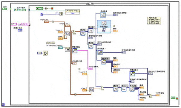
Due to limited machine functions, the program is divided into three parts: generation, collection and processing. Waveform data are calculated according to the results of signal modeling (see "1.3 Composite Signal") and are saved to a file. The waveform generation program begins by reading the waveform data and writing the waveform data into the arbitrary waveform generator. Then, the arbitrary waveform generator is called to generate the desired signals. Under the control of the DAQPilot-related modules, the digitizer begins signal collection. The collected data are stored into a file for subsequent use. The demodulation program calls the above-mentioned waveform file and performs demodulation and operations on the file, thereby completing signal analysis. Figure 3 shows a block diagram of the signal generation and collection program, and Figure 4 shows a block diagram of the demodulation and operation program.

Figure 3. Signal Generation and Collection Program.
Figure 4. Signal Demodulation Program.

3. Operating Results


Hardware components are connected according to the designed hardware structure, and waveform information is set. The baseband signal is a 30Hz sine wave. The frequency modulated (FM) subcarrier is at 9960Hz, with a frequency deviation of 480Hz and a modulation index of 0.3. Considering machine performance and the operating time, the VOR signals are at 1MHz by way of example. The waveform obtained from calculation is saved into a file so as to be called by the waveform generation program. The waveform generation program begins with equipment initialization and parameter adjustment. Then, the card address is set. The power is -10dBm, the center frequency is 1MHz, and the mode is "Arb Waveform". Once the waveform file is called, IQ modulation is applied, wherein I is the modulation signal and Q is 0. When writing data, the same sampling rate as that used in the generation process is selected to ensure that the signals generated have the correct frequency spectrum. [12]


While the signal generation module continues operating, the digitizer is called to perform signal collection. Similarly, a virtual channel must be set. The measuring span is set at ±1V, and the signal type is "AI Voltage". The sampling frequency must satisfy Nyquist's theorem and is set at 8MHz in this study. The sampling clock is set at "Continuous Samples", with the continuation time being 1 second. The sampled data can be displayed in the waveform diagram in real time and, by means of "Write waveform data into file.vi", saved into a file for subsequent use.


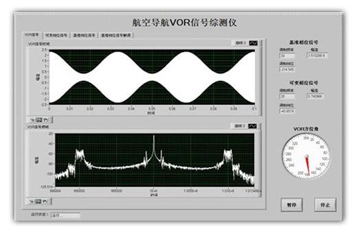
In order to realize signal measurement and verification, the collected waveform must be demodulated to restore the corresponding information. The collected spatial VOR composite signal is subjected to interference demodulation to obtain the outside envelope of the spatial composite signal, which includes a 30Hz variable-phase signal and a 9960Hz FM subcarrier. The 30Hz variable-phase signal can be directly obtained with a 30 Hz filter. The time-domain and frequency-domain waveforms, as well as the frequency, phase, amplitude, and similar information, of the 30Hz variable-phase signal can be seen on the front panel. The 9960Hz subcarrier is filtered and frequency discriminated to obtain the 30Hz reference-phase signal, whose corresponding parameters can also be seen on the front panel. The phase difference between the reference-phase signal and the variable-phase signal provides information of the current direction, which information is read as the VOR azimuth. Figure 5 shows the front panel after the aforesaid operation. During program operation, all the tab pages can be displayed in turn. By pressing the "Pause" button on the lower right corner, the current tab page can be locked.

Figure 5. Front Panel of the Testing Apparatus.

Conclusions


Nowadays software-defined radio technology has found extensive application in military and civil communications. Testing equipment based on this technology is open and flexible and is therefore more promising than conventional equipment. On the other hand, digitizers are the key to transition from analog signals to digital signals. It has been verified that the PCI-9846 high-speed digitizer of ADLINK is easy to install, has a user-friendly interface, can be conveniently used in the LabVIEW environment, is well capable of accurate collection of complex analog signals and analog-to-digital conversion, and can store the collected signals into waveform files for later use. Due to technical limitations and the performance of the computers used, this study was unable to sample at higher frequencies and conduct more signal processing experiments. Hence, further research and improvement efforts are called for.


References:
[1] Dong Qinpeng, Xiong Huagang. Design and Realization of Automatic Test System Based on Aircraft Electronic Equipment. Modern Electronics Technique [J], 2008, 21, 146-149.
[2] Lu Yiqing. New generation Avionics Testing Equipment. Foreign Electronic Measurement Technology [J], 2000, 1, 8-11.
[3] Baidu Encyclopedia. Software-Defined Radio [OL]. [2010.11.27]. http://goo.gl/lKi0D.
[4] Dong Qinpeng, Xiong Huagang. Design and Realization of Automatic Test System Based on Aircraft Electronic Equipment. Modern Electronics Technique [J], 2008, 21: 146-149.
[5] Zheng Lianxing, Ni Yude. DVOR VRB-51D Doppler Omnidirectional Signal [M]. Beijing: China Civil Aviation Publishing House, 1997: 8-15.
[6] Rockwell Collins Company. VOR-700 Receiver Component Maintenance Manual. 17th Revision. Printed in the United States of America, 2006: 71-76.
[7] Xiang Xin. Theory and Technology of Software-Defined Radio [M]. Xi'an: Xi'an University Press, 2008:14-19.
[8] ADLINK Technology Inc. PCI/PXI-9816/26/46 4-CH 16-Bit 10/20/40 MS/s Digitizer with 512 MB SDRAM User's Manual. ADLINK Technology Inc, 2009: 11-12.
[9] Dai Pengfei, Wang Shengkai, Wang Gefang. Testing Engineering and LabVIEW Applications [M]. Beijing: Publishing House of Electronics Industry, 2006: 13-15.
[10] Song Guan, Guangbo Wu. Study on a VOR Signal Generator Based on Software-Defined Radio [C]. ICTIS2011, Wuhan.


Related ADLINK Links:

  • More about ADLINK Digitizers
  • More about PCI-9816/9826/9846
Application of High-speed Digitizers in Electronic Time Fuse General Testing Systems 回列表 Test Systems for High Speed Data Streaming Applications
  • 關於我們
  • 使命與願景
  • 企業永續
  • 投資人關係
  • 新聞與活動
  • 加入凌華
  • 聯絡我們
  • 全球據點
  • 全球經銷商
  • 服務
  • 諮詢技術專家
  • 合作夥伴
  • eRMA服務
  • 關注我們
隱私權政策
Cookie 政策
網站地圖
關於凌華全球據點支援
  •    
  •    
  •    
  •    
Copyright © 2025 ADLINK Technology Inc. All Rights Reserved.
TEL:(03) 216-5088 TEL:(03) 216-5088 FAX:(03) 328-5706 Email:tw@adlinktech.com Address:桃園市龜山區華亞一路66號