Maggie Huang,
ADLINK Technology Inc.
|
 Machine vision has been widely used in production and quality detection applications across many industries for several years and can improve detection precision and increase production speed, making it a key component for most production equipment. The majority of imaging systems available on the market today use an area-scan camera to capture and analyze images. However, the size of products (such as PCBs, LCD panels, and wafers) has increased beyond the precision, resolution, and speed capabilities of area-scan cameras. Line-scan cameras offer the resolution and high-speed image capturing capacity to meet growing industry trends.
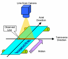
Line-scan imaging systems rely on motion to capture an area image-a completely different model than the simple exposure method used by area-scan imaging systems. In order to design line-scan image detection systems, developers familiar with area-scan detection need to understand the methodologies behind line-scan sampling, how to select components, and most importantly, how to obtain accurate and equal ratio images.
Line-Scan Imaging System Architecture and Components
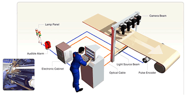 The architecture of a line-scan imaging system is comprised of a controller with two major elements: a vision control axis and motion control axis. Vision components include a line-scan camera, lens, lighting, and frame grabber. The architecture of a line-scan imaging system is comprised of a controller with two major elements: a vision control axis and motion control axis. Vision components include a line-scan camera, lens, lighting, and frame grabber.
Motion control components may include a motor, motor driver, motion controller card and/or programmable logic controller (PLC). A sensor or position comparator is often used to help perform object location detection.
In addition to motion control, the system may also perform image capturing and processing, utilizing a large share of system resources. Most large scale line-scan systems have a dedicated computer to process data acquired from a high-resolution line-scan camera to meet timing and accuracy requirements. Proper system design and component selection are vital for each specific application.
Line-Scan Cameras
Current line-scan cameras offer resolutions of 512, 1024, 2048, 4096, 8192, and 12288 pixels. Most system developers new to line-scan systems typically select a camera that meets target precision requirements without taking into account how its interface specifications will affect frame grabber selection. System developers must also consider:
- suitability of the camera's design features for the system
- line-rate calculation method
- availability of 4X and 8X scan speeds offered by certain line-scan cameras
1. Data Interface
The data interface standards for digital industrial cameras and frame grabbers include: RS-422, RS-644 (also known as Low Voltage Differential Signal, or LVDS), Channel Link, and Camera Link.
- RS-422 and RS-644 (LVDS) interfaces were the earliest standards. A 68-pin or high-density 100-pin connector is typically used depending on data format. However, signal pin definitions and cables differ between manufacturers, making camera and image card selection difficult.
- The Channel Link interface was originally the standard for data transfer for digital flat-panel displays and uses the LVDS signal format. The benefits of this interface include a lower pin count while maintaining high data throughput and compatibility with the Camera Link standard (both Channel Link and Camera Link use the same signal format, but Channel Link specify a standard connector, requiring customized cables for different manufacturer's products).
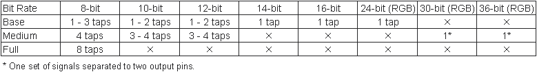
- The Camera Link standard was created by a group of camera and image grabber manufacturers and is based on Channel Link. Camera and image card signals were greatly simplified with the introduction of standardized connectors, eliminating the need for customized cables. Base, Medium, and Full Configurations were also defined for signal pin standards and data throughput.
2. Line-Scan Camera Data Output Forms
Current line-scan cameras typically do not have a clock rate faster than 60MHz. Yet some systems offer 80MHz, 160MHz, and even 320MHz speeds by utilizing various output methods to increase image sampling rates. Typical line-scan cameras use the following output methods: single tap, dual taps, triple taps, quad taps, and octal taps.
|
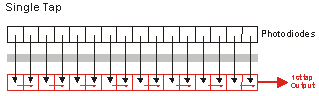
Single Tap
Typically used for low resolution or low speed line-scan cameras, the single tap method features a completely linear CCD where each photodiode converts detected light into an electric charge signal and transmitted through a single output.
Line Rate = Camera Data Clock / Camera Pixels
|
 |
|
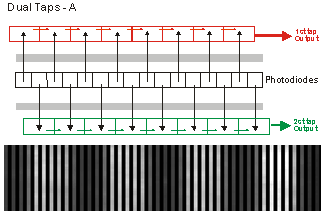
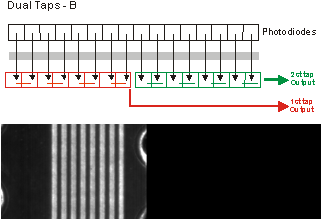
Dual Taps - Even/Odd Output
Typically used for low resolution or low speed line-scan cameras, a single tap method features a completely linear CCD where each photodiode separates detected light into odd and even components, which are converted into electric charge signal and transmitted through dual outputs.
Line Rate = (Camera Data Clock / Camera Pixels) x 2
If the camera data output mode is set to single tap, then the resulting images would appear similar to the example to the right with vertical gaps. These black gaps between pixels will be even more apparent if the image is enlarged.
|
 |
|
Dual Taps - Front and Rear Output
This design is similar to the two designs described above. The main difference is each photodiode of the linear CCD separates detected light into front and rear components, which are converted into electric charge signal and transmitted through dual outputs.
Line Rate = (Camera Data Clock / Camera Pixels) x 2
If the camera data output mode is set to single tap, then the resulting images would appear similar to the example to the right with half the image missing.
|
 |
|
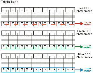
Triple Taps
Typically used for RGB tri-CCD line-scan cameras, a prism separates light into red, green, and blue components based on wavelength (red being the longest, then green, and blue the shortest). Each CCD will convert the light into an electric charge signal for output.
Although each CCD has an independent data clock, data still needs to be combined in order to become a linear color image. Hence, actual speed is not improved.
Line Rate = 3 x [Camera Data Clock] / [Camera Pixels] / 3
The first "3" is for each of the RGB signals. The last "3" is to recombine the colors into a single image.
|
 |
|
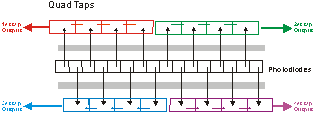
Quad Taps
Typically used to improve the speed of high resolution line-scan cameras, two sets of even and odd and front and rear outputs are generated to improve image capture speed by 4X.
Line Rate = (Camera Data Clock / Camera Pixels) x 4
|
 |
|
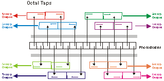
Octal Taps
This design is currently available for high-resolution (12288 pixel) equipment. Front and rear segments are each separated into four sections for 8X the image sampling speed. Therefore octal taps data output can speed up line period even for very high resolution cameras.
Line Rate = (Camera Data Clock / Camera Pixels) x 8
|
 |
Timing Delay Integration (TDI ) line-scan cameras are also available:
|
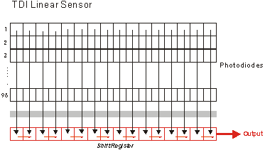
TDI Line-Scan Camera
This unique CCD structure consists of 96 rows of photodiodes that accumulate light detected from a single exposure. The accumulated light is converted to an electric charge signal and sent to a single output. Because the accumulated luminance is greater than that of typical line-scan cameras, TDI cameras are suited settings with low light availability.
TDI cameras are highly dependent on consistent sampling rate and motion speed. If the motion speed is unstable, images will be blurry.
|
 |
3. Line-Scan Camera Line Rate Calculation Method
The method for line rate calculation of line-scan cameras is as follows
Line rate (scan frequency) = [camera data clock] / [camera resolution]>
For example, if the camera data clock is 40MHz and the camera resolution is 8192 pixels,The line rate = 40MHz / 8192 pixels 4.8KHz (some manufacturers may quote a specification lower than the calculated amount).
In other words, this camera can sample approximately 4800 lines of 8192 pixel image data every second.Since the line period = [line rate]-1, this camera would take approximately 200?s to scan one line.
4. Field of View Calculation for Line-Scan Cameras
Field of view (FOV) = [pixel cell size] x [number of pixels] x [working distance] / [focal length]
For example, for a camera with a 10?m pixel size, 2048 pixels, 160mm working distance, and 55mm focal length,FOV = 10?m x 2048 pixels x 160mm / 55mm = 59.58mm
Line-scan camera resolutions vary as a result of differing CCD sensor production methods. In addition, the photodiodes on each CCD, which are the actual physical pixels, may not be uniform in size. The result is that two different 2048 pixel line-scan cameras may have CCD pixel cells of 10µ and 7µ, respectively, and will have two different FOVs when using the same working distance and focal length.
Frame Grabber Selection
Frame grabbers can be separated into two general categories: Digital Signal Processing (DSP) and non-DSP. DSP frame grabbers are more expensive, but offer post-sample processing on-card (such as white balancing, LUT conversion, filtering, shading correction, scan-delay compensation), thus conserving system resources. Non-DSP frame grabbers are typically faster and offer direct memory access (DMA) functionality. The system then processes the data as programmed. Although DSP grabbers can pre-process data to conserve system resources, most manufacturers do not release source code for user customization. Because of flexibility and price, non-DSP cards are the popular choice.
Other important factors for frame grabber selection include data throughput and data interface. The most common PCI bus interfaces are 32-bit/33MHz and 64-bit/66MHz. When deciding on bandwidth requirements, users often fail to take into account the requirements of other PCI peripherals, such as LAN cards. Frame grabbers with onboard memory are recommended to avoid data loss if available PCI bandwidth limited.
Another factor to be aware of is that different line-scan camera interface data formats and may require different frame grabbers. Channel Link and Camera Link data formats are compatible and any Camera Link frame grabber can be used. As mentioned above, Camera Link configurations include: Base Configuration, Medium Configuration, and Full Configuration. Each configuration offers differing data throughput and supports Camera Link camera output modes as defined below:
Light Source Selection
It is extremely important not to use an AC powered light source with a line-scan imaging system as is often used in area-scan applications. Only DC power light sources should be used for line-scan applications.
|
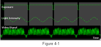
Figure 4-1 illustrates an oscilloscope image of an area-scan camera (sampling speed ~30fps) under regular indoor fluorescent light (AC power, 60Hz). Fluorescent light frequency does not significantly impact on camera exposure time and users can still obtain images with even luminance.
|
 |
|
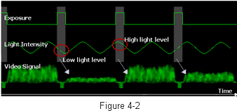
Figure 4-2 demonstrates the fast shutter speed of an area-scan camera. With the shortened exposure time, images will be captured under uneven luminance.
|
 |
|
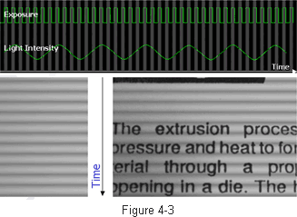
Line-scan exposure times are typically in microseconds. Using a fluorescent light source will result in an uneven luminance pattern as shown in Figure 4-3.
|
 |
Lens Selection
Lenses with wider apertures are best. F-mount adapters are the preferred choice for line-scan cameras 2048 pixels and greater. However, F-mount lenses don't offer the selection and cost benefits of C-mount and CS-mount lenses; especially for film camera applications. High-resolution (8196 or 12288 pixels) line-scan camera manufacturers may support the F-mount specification in addition to proprietary adaptors as well as offering software-based shading correction to resolve uneven luminance issues.
Motion Control Types and Characteristics
PLC vs. PC Based
PLC and PC-based motion control logic and interfaces differ greatly.
PLC architectures use serial signals (RS-232 or RS-485) to send motion, and position commands. This type of architecture works well for area-scan systems. But for line-scan systems, a bridge is needed to convert signals before transfer to the image processing platform due to greater triggering requirements and the fact that PLC AB phase encoder signals cannot be used as a trigger. Below is a list of common methods:
- Add an additional computer with a position comparator card that can compile encoder signals.
- Add a converter module to the encoder to convert the signal to TTL or LVDS.
- Add a position comparator (expensive, rare) or optical scale.
- Other bridging methods.
Although these methods can perform position comparisons, a bridge must be used, which increases the likelihood of signal loss for high-speed applications.
PC-based architectures use motion controller cards to send command pulses to transmit position and speed. An encoder is used for the motor's feedback pulse. During processing, position comparison can be performed (some motion controller cards do not support this function). After arriving at a given position, a TTL or LVDS signal can be used as an external synchronization trigger or continuous trigger signal to trigger line-scan camera sampling. Because a bridge is not needed, synchronized sampling of each line is accurate. For these reasons, PC based motion control systems are recommended for line-scan imaging applications.
Belt / Linear Guideway / Ball Screw
Belts, linear guideways, or ball screws are commonly integrated with the motion controller in motion systems.
Belts - Not recommended for use in the main line-scan sampling axis. Belt key distance is not accurate enough for line-scan applications and line skipping may result.
Linear Guideway - Easily missteps under high speeds or if not well maintained.
Ball screws - Suffers from backlash. However, since the backlash for each ball screw is fixed (most manufactures provide backlash specification data), compensation can be calculated to improve line-scan position comparison and triggering.
Use of Optical Scale - Friction from long-term motion equipment use can produce image deformities. Both area-scan and line-scan platforms typically require an absolute level of precision. An optical scale is recommended to maintain this level of precision.
Obtaining Equal Ratio Line-Scan Images
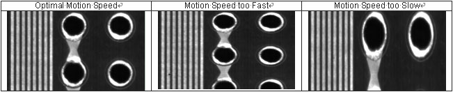
Line-scan camera can only detect one line at a time within its FOV. Motion is used to combine each scanned line into a complete image. At least one axis of motion is required. However, continuous motion will not necessarily produce an accurate image. If motion speed is not consistent with the sampling rate, image deformation will occur and line segment data will be lost. The tests below describe how to obtain accurate equal ratio line-scan images.
Basic Tests
1.Motor Motion Control
The majority of PC-based systems use a controller card to communicate with the motor driver for motor positioning. It is vital for the command pulse sent by the controller card to modulate in synch with the feedback pulse of the encoder, and that the calculated distance moved is the actual distance moved with each command pulse.
Implementation Test
a. Ensure that command pulse = feedback pulse.
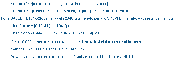
b. After sending a command pulse, measure actual distance moved. For example: If 10,000 command pulses are sent, and when the actual distance moved is 10mm, one pulse will equal one ?m. With this data, line-scan trigger positioning will be more accurate.
2.Line-Scan Camera Sampling Test
Because line-scan cameras do not have the large sensor area of area-scan cameras, first time line-scan camera users may incorrectly assume the camera or frame grabber is malfunctioning if the entire image is not formed. Below are some simple methods to check camera sampling.
a. Connect the line-scan camera to the frame grabber. Use the configuration utility provided by the camera's manufacturer to set the internal synchronization mode. Next, set the sampling configuration of the frame grabber to use the camera's configuration file. Attaching a lens is not necessary. Point the line-scan camera's CCD sensors towards a light source and take a sample. The light should be visible.
b. Another method is to use the camera's test image/pattern function. Use the camera's configuration utility to enable testing of image output. The test image should match what was sampled.
c. If no image is sampled or the frame grabber does not register a signal input, check the following:
- Camera to frame grabber port setting error - ensure that port used matches port setting.
- Line-scan camera power is not connected.
- Camera signal cable failure - try another cable.
- Camera has malfunctioned - try another camera.
d. Of course the frame grabber can also malfunction. Try re-installing the driver or using a difference PCI slot before returning the card.
Integration Test
1. Line-scan camera sample with light source
After making certain that both line-scan camera and frame grabber are functioning normally, place the camera and light source in the required positions for operation. Check that the light source can be detected by the CCD sensors (Note: Linear light sources must be properly aligned with linear CCDs). Place a sheet of white paper on the test area and take a sample. This will confirm correct light source position, angle, and uniformity.
2. Motion speed and camera sampling rate
The motion required for continuous sampling is heavily dependent on the relationship between line-scan line rate and motion speeds. If the speed is out of sync, the image will become distorted. Optimal motion speed must be determined to prevent distortion. Use the following formulas to calculate the number of command pulses for optimal speed.
3. External Trigger Synchronized Sampling
Motion speed data may not be as precise as desired. However, precise position comparisons are required to produce an equal-ratio image. External trigger signals are typically TTL or LVDS and are generated by the encoder's position arrival signal. To compensate for minor distance discrepancies, some manufacturers provide a rate conversion ratio function to adjust the ratio between line pitch and encoder pitch.
Conclusion
Like other technologies, test and measurement equipment requirements are continuously changing. PC based line-scan cameras offer the resolution and high-speed capturing capability to meet the image sampling needs of leading-edge technologies. Application of the principles discussed in this article will ensure a smooth transition from an area-scan to a line-scan imaging system through considering and understanding the requirements for efficient line-scan camera operation in higher resolution and high-speed sampling.
 BACK BACK
Related ADLINK Links:
ADLINK Measurement & Automation
|


