|
Industry Standard Mezzanine Modules
(2003.07)
I/O expansion for CompactPCI and VME based systems is typically done using native form factor cards. The overhead required to implement a simple function on a CompactPCI or VME card can at times be excessive. Simple I/O functions require a lower cost and smaller form factor standard. The need for a mezzanine standard was recognized by the industry and released by the IEEE as P1386 and P1386.1 in the summer of 2001. These standards have been enhanced by PICMG and VITA to meet telecommunications and higher throughput requirements. Although the modules were targeted for CompactPCI and VME they can be used on any form factor that can provide the mechanical, electrical and signaling requirements. This article will introduce the PCI Mezzanine Card (PMC) and the extensions added by PICMG and VITA.
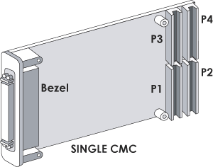
The PMC standard is a combination of two IEEE standards, IEEE P1386 Standard Mechanics for a Common Mezzanine Card Family (CMC) and IEEE P1386.1 Standard Physical and Environmental Layers for PCI Mezzanine Cards (PMC). The P1386 standard defines the form factor, connector, and electrical interconnects, P1386.1 maps PCI bus signals onto P1386 cards. The CMC specification defines two modules sizes single (74mm x 149mm) and double (149mm x 149mm). The bezel on a CMC protrudes through the carrying card to allow access to I/O. Interconnects to the CMC are through 4 connectors labeled P1, P2, P3 and P4. The drawing below shows a single wide CMC.

Figure 1 Single Wide CMC
As mentioned, the CMC provides the mechanical and interconnect standard for a mezzanine module. The PMC specification maps PCI signals onto CMC defined interconnects. The 32 bit PCI bus requires two 64 pin connectors, P1 and P2. The 64 bit PCI bus requires three 64 pin connectors P1, P2, and P3. The remaining 64 pin connector P4 is used to route I/O signals to a Rear Transition Module (RTM). The PCI specification allows 3.3 or 5V signaling. Manufacturers of PMC modules are required to key the PMC module to denote the required V(I/O). The PMC can be keyed for 3.3V, 5V or universal operation. Users of PMC modules need to make sure that the V(I/O) provided by the carrier is compatible with the PMC V(I/O). It is not uncommon for users to remove the V(I/O) key from the PMC module because it is "in the way", when in reality the PMC module and carrier card do not support compatible voltages.
One of the first enhancements made to the PMC specification was initiated by the VITA Standards Organization. The PMC specification relied on the carrier for the PCI bus monarch. The monarch is defined as the main PCI bus processor. It is the processor that performs the bus enumeration and handles interrupts. The PMC specification expected that the monarch was on the carrier card, no provisions were made to allow the PMC module to be a monarch. The VITA-32 specification defined the signals necessary to allow a PMC module to be a monarch. This specification opened the door for a new family of PMC modules namely Processor PMCs. Besides the additional signals to support monarch mode, VITA-32 also addressed some of the thermal and component height restrictions that limited the ability of designers to place processors on PMC modules.
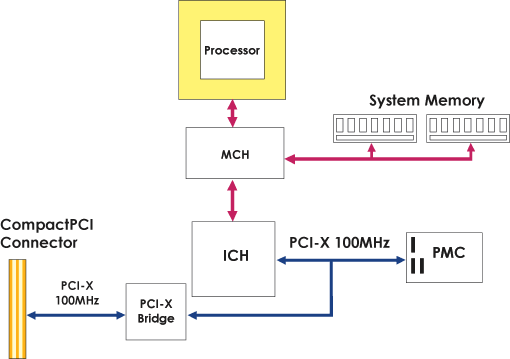
The original PMC specification supported 33MHz and 66MHz PCI operation. In 2002 the VITA Standards Organization recognized the need to add support for PCI-X operation. The VITA-39 specification added the PCIXCAP signal to the PMC P1 connector. This signal allows the PMC to support 66, 100 and 133MHz PCI-X transactions. The VITA-39 specification also included simulation work necessary to define the maximum number of PCI loads that could be supported at the various operating frequencies. This is important since most PMC carrier cards have other local PCI devices. The sharing of the PCI bus between on card devices and the PMC can lead to other unforeseen operational challenges. If the local PCI segment is running at PCI-X 133MHz and a 33MHz PMC is installed on the segment then the segment will run at 33MHz. Care should be taken when using PMC carriers that support PCI-X speeds to ensure that the impact to any other device that shares the PCI bus segment is identified. In the example below, a PCI-X 100MHz bus is shared between a PMC and PCI-X bridge. When the PMC is not installed, this bus will run at PCI-X 100MHz. If a 33MHz PCI PMC is installed then the segment will run at 33MHz PCI impacting the throughput of the bridge.

Figure 2 Possible CPU card PCI-X Bus interconnect
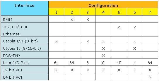
The PCI interface has served the CompactPCI and VME markets well, but lacked the ability to handle packet based data transport interfaces required by network processors. In August 2001, PICMG released PICMG 2.15 PCI Telecom Mezzanine Card (PTMC) specification. This specification was intended to support 4 popular industry standard telecom bus interfaces (H.110, Utopia Level 2, POS-PHY, and RMII) as well as support for the existing 32 and 64 bit PCI bus. PICMG released an ECR to PICMG 2.15 at the end of 2002. This ECR expanded the number of configurations supported from 4 to 7 by adding Ethernet capabilities to TDM and UTOPIA configurations. The flexibility provided by PICMG 2.15 comes at a price, namely ease of use. The PICMG 2.15 subcommittee had to live within the pins available in the PMC specification. This limitation required that specific configurations and pin usages be documented and also required that the pins traditionally used for the upper 32 bit of 64 bit PCI interface be redefined to support the new I/O capabilities limiting PTMCs to 32 bit PCI interfaces. When using PTMCs it is important to verify that the PTMC and board it plugs into (carrier card) support the same configuration. The table below defines at a high level some of the PTMC configurations available.

The capabilities of a PTMC and Carrier Card are determined by its configuration type. As an example, a PTMC and Carrier Card that supports configuration 5 (2 Ethernet and 32 bit PCI interfaces) is referred to as a PT5MC and the Carrier Card as a PT5CC. It should be noted that the number of PMC I/O lines available to support rear I/O is impacted by the various configuration types. When selecting the type of PTMC take into consideration the interface and rear I/O requirements.
|