| |
| Application in High-Speed PCB Optical Mask Printers (2002.11.21) | |
| Purpose | |
| Drive a high-speed PCB (printed circuit board) optical mask printer system. | |
| Solutions | |
|
When manufacturing a PCB, generally the PCB file is generated by electronic design software (such as Protel, ORCAD, and so on) and delivered to a PCB manufacturer, who prints out an optical mask based on the PCB graphic file using a computer. When the optical mask is used for photocomposing, the graphic information is copied to an empty PCB (via sensitization), which in turn is etched to remove the un-sensitized copper foil. The resulted PCB with the sensitized copper foil is what is needed.
More and more optical mask printers nowadays are computer controlled. Most of the printers are controlled with a circuit. This controller communicates with the computer via a digital interface. Originally an ISA bus cards is used to provide the digital interface to transmit 4 bits in each batch to the peripheral via 4 DO channels, with the timing offered by an external clock. With advancements in technologies, the printed board is ever increasingly densified, leading to more and more data transmission capabilities. Since the legacy ISA bus is limited by transfer rate, most advanced foreign equipment use high-speed PCI bus cards instead. In such a situation, some optical mask printer vendor have developed high-speed PCB optical mask printer with ADLINKS PCI-7300A card. |
|
| Details | |
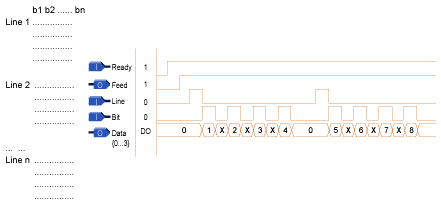
As a high-speed DIO card that offers sampling frequency up to 20MHz, the PCI-7300A is suitable for transmission of high-speed digital signals, with extremely flexible external clock and handshaking methods. The optical mask printer functions like a laser printer, except the laser printer receives output through the printer port and uses paper as media, while the optical mask printer receives output under the control of a specific card that delivers high speed transmission capacities of high data volume necessary for the printer, which has resolution ranging between 1000 and 8000DPI. In addition, the media for the optical mask printer is film. The printer has a built-in control circuit which can receives parallel data and drives the mechanical parts. The signals bouncing between the control circuit and the computer is of differential type, with interface signals as follows (view from the printer side):
1 Ready (O): Active high, indicates the printer is ready |
|
| The operation is as below: | |
|
1. Once the self-test has been performed and passed, the device generates the Ready signal. 2. On listening for the Ready signal, the program prepares the data that is to be outputted and sends a Feed signal to the device. 3. The device sends a Line Sync signal indicating a new 4-line batch is to be started. 4. The device sends Bit Sync signal to indicate the start of a bit in lines and the device outputs 4 bits data (4 Line X 1 bit). The 4th step is repeated until a new Line signal is available and data for the next 4-line will be sent. 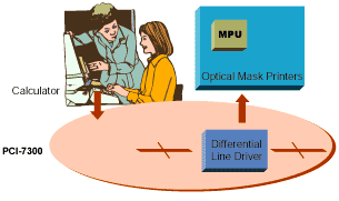
| |
 |
|